
- the rotary switch of modes of functioning of external lighting;
- instrument lighting brightness control (potentiometer);
- headlight optical axes direction control;
- fog light switch;
- rear fog light switch.
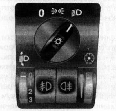
17.6. Ambient lighting switch panel/instrument cluster illumination
Note: Depending on the configuration, the appearance and design of the regulators may differ from those shown in the illustrations. However, their symbols and control principle are the same as those described below.
Rotary switch for outdoor lighting modes
The rotary switch is located at the top of the switch panel (see illustration 17.6) and can be installed in one of 3 positions:
ABOUT In this switch position, all outdoor lights are off.
When the vehicle is equipped with a daytime running light system, even if the rotary switch is set to «ABOUT», the dipped beam will be activated automatically when the ignition is turned on. In this case, the instrument lighting remains off.
Instrument illumination brightness control (potentiometer)
The illumination of the instruments is activated when the external lighting devices are switched on. The brightness of the backlight can be adjusted using the roller control built into the lower right corner of the switch panel (see illustration 17.6).
Adjustment is made by turning the roller adjuster in the appropriate direction.
Note: On models equipped with a central information display, the brightness of the screen is adjusted simultaneously with the brightness of the instrument illumination.
Headlight optics direction adjuster
Manual adjustment of the tilt of the optical axes of the headlights
Roller adjuster for the direction of the optical axes of the headlights (with appropriate equipment) built into the lower left corner of the switch panel and has four positions (see illustration 17.6).
The regulator allows you to change within certain limits the direction of the optical axes of the headlights in the vertical plane. The slope of the optical axes of the headlights is the stronger, the larger the number selected on the regulator scale (see illustration 17.6). With an increase in the number of passengers and the degree of loading of the car, to prevent blinding of oncoming drivers, as well as vehicles in front, increase the angle of inclination of the light beams.
Rotate the knob to set it to the desired position. Adjustment is carried out with the dipped beam headlights on (see above).
Recommended settings for Corsa C/Combo/Combo Tour:
- 0 - only the front seats are occupied;
- 1 - all seats are occupied;
- 2 - all seats and cargo in the luggage compartment are occupied;
- 3 - the driver's seat and cargo in the luggage compartment are occupied.
Recommended settings for Corsa-van/Combo-van:
- 0 - seats are occupied;
- 1 - seats are occupied and the luggage compartment is half loaded;
- 2 - all seats are occupied and the luggage compartment is fully loaded;
- 3 - the driver's seat is occupied and the luggage compartment is fully loaded.
Automatic adjustment of the tilt of the optical axes of the headlights
On models equipped with a xenon headlight system, the angle of inclination of the optical axes of the headlights is adjusted automatically. If a malfunction occurs in the automatic adjustment device, the corresponding warning lamp is activated on the instrument cluster (see Section 16) - the problem must be rectified immediately.
Asymmetrical headlight distribution
All models described in this manual are equipped with asymmetrical low beam headlamps. The asymmetrical headlights improve visibility of the road on the front passenger side. If you have to travel to a country with left-hand traffic, asymmetric light can cause blinding of oncoming drivers and cause accidents. Sometimes this mode needs to be removed for other reasons.
To eliminate the effect of asymmetric light distribution, it is necessary to install special caps on the headlights - contact the official representative offices of Opel, where they can select the appropriate equipment for you.
Fog light switch
If equipped, the fog light switch
Fog lights are activated by pressing the switch, if the ignition and exterior lighting of the car are on, the corresponding indicator on the instrument cluster should light up (see Section 16). Pressing the same button again will deactivate the fog lights - the indicator on the instrument cluster goes out.
Rear fog light switch
When equipped, the rear fog light switch
The lights are activated when the switch is pressed, if the ignition and exterior lighting of the car are turned on, the corresponding indicator on the instrument cluster should light up (see Section 16). Pressing the same button again will deactivate the rear fog lamps - the indicator on the instrument cluster goes out.
Note: When towing a trailer, the rear fog lights turn off.
Hood latch release lever
The hood release lever is located under the instrument panel to the left of the steering column (see illustration 15.1). For a description of the hood opening procedure, refer to Section 4 (see Part A).
Visitor comments