


Contents: Rotary switch for outdoor lighting…⬇ Instrument lighting brightness…⬇ Headlight optical axis direction…⬇ Bonnet Lock Latch Release Lever ⬇
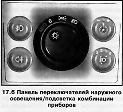
The exterior lighting/instrument lighting switch panel is integrated into the instrument panel to the left of the steering column. Depending on the vehicle's equipment, it may contain up to five controls (see illustrations 15.1, 17.6):
- rotary mode switch
- functioning of outdoor lighting;
- instrument lighting dimmer (potentiometer);
- headlight optical axis direction regulator;
- fog light switch;
- rear fog light switch.
The mounting sockets that are not occupied by the installation of the corresponding control element are covered with decorative plugs.
Rotary switch for outdoor lighting modes
The rotary switch is located in the center of the switch panel (see illustration 17.6). Depending on the configuration, the rotary switch can be 3- or 4-position:
- In this switch position, all external lighting devices are turned off.
- When the rotary switch handle is moved to this position, the front and rear side lights and the license plate light are turned on - the corresponding indicator on the instrument cluster should light up (see Section 16).
- When the rotary switch handle is moved to this position, the low beam headlights are turned on in addition to the previously activated running lights.
- AUTO (with appropriate equipment) The control of the external lighting devices is performed automatically, depending on the intensity of external illumination. When the ignition is on, in poor lighting conditions, the parking lights and license plate illumination are activated automatically, and when the engine is running, the low beam headlights are turned on. The external lighting devices are switched off when the engine is stopped and the ignition is turned off, respectively.
Note: The authors of this manual recommend that you always set the switch to the AUTO position.
If the Daytime Running Lights (DRL) system is equipped, when the rotary switch is set to the "O" or AUTO position, the front and rear parking lights and license plate light will be activated when the ignition is turned on, and the low beam headlights will be activated when the engine is started.
Note: The high beam headlights will only be activated after the left steering column switch is switched to the appropriate position (see above).
Instrument lighting brightness controller (potentiometer)
The instrument and information display illumination (see below) is activated when the ignition is switched on. The brightness of the illumination can be adjusted using a potentiometer, the rotary knob of which is built into the upper right corner of the switch panel (see illustration 17.6).
To adjust, first activate the external lighting (see above), then release the rotary knob of the regulator from the seat by pressing. Then turn the knob to the right/left until it stops and, holding it in this position, achieve the required brightness of the backlight: to the right - increase the brightness, to the left - decrease the brightness. After completing the adjustment, press the knob into the seat until it locks.
Some versions feature automatic adjustment of instrument lighting depending on lighting conditions - it is activated when the ignition is turned on, the light-sensitive sensor is built into the housing of the interior rearview mirror.
Headlight optical axis direction regulator
Manual adjustment of the tilt of the optical axes of the headlights
Headlight Axis Direction Control Button (with appropriate equipment) built into the lower right corner of the switch panel and has four fixed positions (see illustration 17.6).
The regulator allows changing the direction of the optical axes of the headlights in the vertical plane within certain limits. The tilt of the optical axes of the headlights is greater, the higher the number selected on the regulator scale. As the number of passengers and the degree of loading of the car increase, to prevent blinding drivers of oncoming vehicles and vehicles in front, increase the tilt angle of the light beams.
To change the setting value, press the regulator button into the seat and turn it left/right to set the desired position. Adjustment is performed with the low beam headlights activated (see above).
Recommended settings for vehicles without ride height control:
- 0 - only front seats occupied;
- 1 - all seats are occupied;
- 2 - all seats are occupied and there is cargo in the trunk;
- 3 - the driver's seat is occupied and there is cargo in the trunk.
Recommended settings of the corrector for cars with automatic adjustment of ground clearance (see Section 25):
- 0 - only front seats occupied;
- 1 - all seats are occupied;
- 1 - all seats are occupied and there is cargo in the trunk;
- 2 - the driver's seat is occupied and there is cargo in the trunk.
Automatic adjustment of the tilt of the optical axes of the headlights
On models equipped with a xenon headlight system, the angle of the optical axes of the headlights is adjusted automatically.
Adaptive Headlight System (AFL)
On vehicles with dual xenon headlights, the adaptive light system serves to improve illumination of the road when turning corners (see illustration 17.7). The light beam is deflected depending on the position of the steering wheel and the speed of movement (starting at about 10 km/h). The maximum angle of deviation of the light beam from the vehicle axis is ±15°.
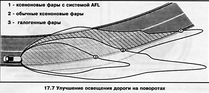
In addition, when the vehicle is constantly moving in a straight line at high speed, the brightness of the headlights in low beam mode is automatically increased, increasing the illumination range.
If there is a fault in the adaptive headlight system, the corresponding indicator lamp (see Section 16) is activated in permanent mode. If the system's turning device fails, the low beam headlight is switched off and the corresponding fog light is automatically switched on to provide emergency road illumination. Contact an Opel service station for assistance as soon as possible.
Disabling asymmetrical headlight distribution
On models with the corresponding configuration, asymmetrical low beam (see illustration 17.7) improves the view of the road from the front passenger side. If you are going to a country with left-hand traffic, the asymmetrical light may cause blinding of oncoming drivers and cause accidents. Sometimes this mode needs to be turned off for other reasons.
The AFL system provides the ability to switch between asymmetric and symmetric light modes. To turn off the asymmetric headlight mode, pull the left steering column switch towards you and, holding it in this position, turn on the ignition - after about 3 seconds, an audible gong will sound, the adaptive light system failure indicator lamp (see Section 16) is activated in flashing mode for approximately 4 seconds.
Note: When the asymmetric light is switched off, this indicator lamp will flash for 4 seconds each time the ignition is turned on.
To return to the asymmetrical headlight mode, you need to follow the same procedure.
If there is no AFL system, in case of need to refuse asymmetrical light, it is necessary to contact the Opel service station to replace/reinstall the headlights.
Fog light switch
If equipped, the fog light switch is integrated into the upper left corner of the switch panel (see illustration 17.6).
The fog lights are activated by pressing the switch, if the ignition and external lighting of the car are on - the corresponding indicator on the instrument cluster should light up (see Section 16). Pressing the same button again will deactivate the fog lights - the indicator on the instrument cluster will go out.
Rear fog light switch
If equipped, the rear fog light switch is integrated into the lower left corner of the switch panel (see illustration 17.6).
The lights are activated by pressing the switch; if the ignition and external lighting of the car are on, the corresponding indicator on the instrument cluster should light up (see Section 16). Pressing the same button again will deactivate the rear fog light - the indicator on the instrument cluster.goes out-no. Note: When towing a trailer, the rear fog lights are turned off.
Bonnet Lock Latch Release Lever
The hood release lever is located under the instrument panel to the left of the steering column (see illustration 15.1). The procedure for opening the hood is described in Section 4.
Visitor comments