
General information
Ventilation, heating and air conditioning systems (with appropriate equipment) make up a single functional unit, which is designed to maintain a comfortable temperature inside the car, regardless of the outside temperature and weather conditions. Depending on the configuration, the set temperature can be adjusted both manually and automatically (climate control) mode. Air enters the passenger compartment through the air intake grilles located outside on the left and right under the windshield of the car (see illustration 18.1). If necessary, it is possible to turn off the intake of outside air. Air is released through special openings in the rear wall of the luggage compartment - to maintain comfortable microclimate conditions in the cabin, do not block them with luggage. The air flow in the ventilation and heating system is heated by passing air through the heater heat exchanger, which is connected to the engine cooling system in parallel with the main radiator. In the air conditioning system (K/V) cooling and dehumidification of the air is carried out by means of a special refrigerant charged into this system, which circulates through a separate closed circuit when the compressor is activated (see chapter 3). Depending on the configuration, the system is equipped with an intake tract carbon air filter, which protects the passenger compartment from the penetration of dirt, dust and pollen into it. For the greatest efficiency of the system and maximum comfort in the interior of the passenger compartment, the filter should be replaced regularly at the next scheduled maintenance of the car.
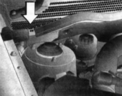
18.1 Air intake
Note: The filter must be replaced without waiting for the next service, if the intensity of the air flow supplied to the passenger compartment noticeably decreases or the windows begin to fog up slightly during the operation of the heater or air conditioner.
Air distribution elements
The air supply to the car interior is carried out through a network of air ducts of the ventilation system, ending in nozzles equipped with fixed or rotary deflectors. The fixed air supply deflectors for blowing the windshield are located in the upper part of the instrument panel under the windshield, and the lower level air duct nozzles are located at the bottom of the panel, in the foot wells.
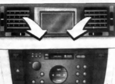
18.2 Swiveling deflectors of upper level central ducts
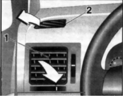
18.3 Rotary side nozzle deflectors (1) and upper (2) upper level air ducts
Air is supplied to the car interior in three main directions:
- On the front level of the driver, front passenger and on the side windows (central, side and upper instrument panel vents), and with the appropriate configuration and on the rear passenger seats;
- For the windshield (instrument panel front deflectors);
- In the footwells of the front seats (lower air ducts).
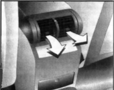
18.4 Swiveling rear passenger vents
The design of the louvered deflectors of the outlet nozzles of the air ducts of the front level allows you to control the intensity and direction of the outgoing flows (the turning element is the deflector grille). By turning the vertical regulator, you can change the intensity of the air flow, up to a complete cessation of its supply (extreme down position). Changing the direction of the air flow is made by redirecting the grilles of the rotary deflectors (central and lateral) in the desired direction by turning the horizontal knob. Changing the direction of the air flow of blowing the rear passenger seats is carried out using the central handle located on the blinds of the corresponding deflector.
HVAC control panel
The HVAC control assembly is placed at the bottom of the console section of the instrument panel.
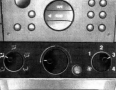
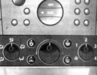
Depending on the configuration, a system with manual adjustment of operating modes or a system with the function of automatic control of the air temperature in the cabin is installed on the car (climate control). The HVAC, heating and air conditioning control unit includes three rotary knobs and several pushbutton switches (depending on configuration) (see illustrations 18.5a, 18.5b and 18.6).
HVAC system with manual adjustment
Activating/deactivating the system and adjusting the airflow rate
Fan Speed Rotary Switch (see illustration 18.5) located on the right side of the HVAC control panel. To activate the system, remove the switch from the 4L position. Returning the regulator to this position allows you to turn off the system, moving the switch to the appropriate position selects the speed mode of the fan, from the minimum (position 1) up to maximum position 4).
Temperature selection
The choice of temperature mode is carried out by a rotary knob located in the center of the panel (see illustration 18.5). When turning the handle from the middle position to the left / right, the supply of cold or heated air will be increased accordingly.
18.5a HVAC control panel with run setting (without air conditioning)
Selecting the direction of airflow distribution
The choice of the direction of distribution of the air flow is carried out by a rotary switch located on the left on the control panel of the system (see illustration 18.5), and provides the following options:
 Air supply to the front level, to the footwells of the front seats and to the rear passenger seats.
 Air supply to the front level and to the rear passenger seats.
 Air supply for blowing the windshield and front side windows.
 Air supply to the foot wells, to the windshield blower and to the rear passenger seats.
 Air supply to footwells and rear passenger seats.
Air circulation mode
The air circulation mode is activated using the
Note: Prolonged use of the circulation mode leads to fogging of the windows and an increase in the stuffiness of the air, therefore it is recommended to activate this mode only if it is really necessary and for a relatively short time. As soon as it is no longer necessary to isolate the passenger compartment, the fresh air supply must be restored.
18.5b HVAC control panel with run setting (with air conditioning)
Pressing the switch button again restores the air supply.
Note: When turning the airflow direction selection rotary switch (see above) in the air supply position for blowing the windshield, the air circulation mode is automatically turned off.
Air conditioning mode (with appropriate equipment)
The air conditioner operates in conjunction with the interior heating and ventilation system. Besides, K/V is used for preliminary dehumidification of air. This mode is only available when the engine is running. On models of the corresponding configuration, A/C is activated by pressing the
Note: At low outside temperatures, the air conditioner will automatically turn off. For accelerated cooling of the air in the cabin, you can temporarily activate the circulation mode (see above). If there is no need for cooling and dehumidification, turn off the air conditioner to save fuel.
Ventilation
Select one of the three positions of the desired air distribution direction using the left rotary switch:
Set the desired temperature mode with the central rotary regulator - the interior will be blown by the flow of oncoming air passing through the heat exchanger or bypassing it (depending on the position of the regulator).
If necessary, use the right rotary switch to activate the system fan at the desired airflow rate (1 to 4).
Visitor comments