
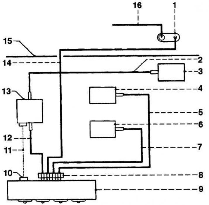
1. Vacuum manifold
2. Blue vacuum hose
3. Vacuum block air recirculation valve
4. Vacuum defroster valve block
5. Brown vacuum hose
6. Vacuum valve block for foot warmer air ducts
7. Green vacuum hose
8. Connector
9. Heater control
10. Air recirculation switch
11. Solenoid valve wire
12. Blue hose
13. Solenoid valve
14. Yellow hose
15. Dividing wall
16. Vacuum hose
The heating and ventilation system is controlled by a group of valves that direct air through the desired air channels.
Heater Control Panel Switches
Removing
1. Disconnect the negative battery cable.
2. Wrap the ends of two small screwdrivers with electrical tape.
3. Insert screwdrivers into the holes on each side of the switch being removed. Lightly press the latches and remove the switch button.
4. Squeeze the latches located on the sides of the switch and remove the switch from the panel.
Installation
Installation is carried out in the reverse order of removal.
Heater control panel
Removing
1. Remove the switches from the control panel.
2. Remove the four handwheels from the heating and air distribution control pins.
3. Take off the radio.
4. Remove the glove box.
5. Remove the five screws on the control panel.
6. Remove the panel from the heater control box.
7. Disconnect the wires from the panel.
Installation
Installation is carried out in the reverse order of removal.
Heater control unit
Removing
1. Remove the control panel.
2. Loosen the screws and remove the block.
3. Disconnect the cables from the control rods.
4. Disconnect the wire from the back of the fan control switch.
5. Disconnect the vacuum hose manifold from the back of the unit.
6. Remove the block.
Installation
Installation is carried out in the reverse order of removal.
Air distribution unit
Removing
1. Drain the coolant and remove the instrument panel.
2. Disconnect the air conditioning pipes from the partition wall of the engine compartment, for this procedure, contact a specialist.
3. Disconnect the air duct from the air vent located on the driver's side.
4. Remove the steering column brace.
5. Remove the bolt and disconnect the ground wire from the dividing partition of the engine compartment.
6. Disconnect the wire from the blower motor.
7. Disconnect the tubes from the heater radiator and drain the coolant into a suitable container and close the tube openings with plugs.
8. On models with air conditioning, disconnect the rear coolant shutoff valve vacuum hose.
9. Disconnect the wire from the recirculation solenoid valve.
10. On non-climate models, disconnect the yellow hose from the air distribution unit.
11. Remove the screws and disconnect the air ducts located in the rear seat footwells from the air distribution unit.
12. Disconnect the blue hose from the recirculation valve vacuum block.
13. On automatic transmission models, disconnect the shift lever cable from the recirculation solenoid valve.
14. Remove the two air distribution unit mounting bolts located near the upper edge of the baffle and one bolt located inside the passenger compartment.
15. Remove the block.
Installation
Installation is carried out in the reverse order of removal (do not forget to replace the old tube o-rings).
Heater radiator
See subsection 4.9.
Blower fan
See subsection 4.10.
Heater control cable - driver's side
Removing
1. Remove the instrument panel to gain access to the air distribution unit.
2. Remove the circlip and disconnect the cable from the control arm on the distribution box.
3. Remove the heater control panel.
4. Remove the retaining ring and disconnect the cable from the end of the control rod.
5. Remove the rope.
Installation
Installation is carried out in the reverse order of removal.
Heater control cable - passenger side
Removing
The procedure is the same as removing the cable from the driver's side (see higher), with the difference that in order to gain access to the cable, it is necessary to remove the air channel located in the front passenger's footwell.
Air recirculation solenoid valve
Removing
1. Disconnect the negative battery cable.
2. Remove the lower trim panel on the driver's side and remove the air duct located in the footwell.
3. The solenoid valve is fixed on the left side of the air distribution unit. Disconnect the hoses and wires from the valve.
4. Unscrew the screw and remove the valve.
Installation
Installation is carried out in the reverse order of removal.
Vacuum Air Recirculation Valve Block
Removing
1. Remove the glove box.
2. Disconnect the wiring harness and air duct.
3. The unit is located on the left side of the blower housing.
4. Disconnect the blue hose from the unit.
5. Disconnect and remove the block.
Installation
Installation is carried out in the reverse order of removal.
Vacuum Defroster Valve Block
The defroster unit is located on the right side of the air distributor and has a brown hose connected to it.
Vacuum valve block for foot warmer air ducts
The unit is located on the right side of the air distributor and a green hose is connected to it.
Visitor comments