


Contents: General information ⬇ Air flow distribution elements ⬇ HVAC control panel ⬇ HVAC system with manual adjustment ⬇ Exploitation techniques ⬇ Heating ⬇ Air conditioning (with appropriate…⬇ HVAC system with automatic…⬇ Use of residual engine heat/air…⬇ Additional information on the HVAC…⬇
General information
Ventilation, heating and air conditioning systems (with appropriate equipment) form a single functional unit, which is designed to maintain a comfortable temperature regime inside the car regardless of the outside air temperature and weather conditions. Depending on the configuration, the set temperature can be adjusted either manually or automatically (climate control) mode.
Air enters the passenger compartment through air intake grilles located on the outside on the left and right under the windshield of the car. If necessary, it is possible to turn off the outside air intake. Air is released through special openings in the rear wall of the luggage compartment - to maintain comfortable microclimate conditions in the passenger compartment, do not block them with luggage.
Heating of the air flow in the ventilation and heating system is carried out by passing air through the heater heat exchanger, which is connected to the engine cooling system in parallel with the main radiator. In the air conditioning system (A/C), cooling and drying of the air occurs by means of a special refrigerant filled into this system, which circulates in a separate closed circuit when the compressor is activated (see Chapter 3). The system is equipped with a carbon air filter for the intake tract, which protects the interior from dirt, dust and pollen. For maximum efficiency of the system and maximum comfort in the interior, the filter should be replaced regularly during the next scheduled maintenance of the car (see Chapter 1, Section 19).
Note: The filter must be replaced without waiting for the next service if the intensity of the air flow supplied to the passenger compartment noticeably decreases or the windows begin to fog up slightly while the heater or air conditioner is operating.
Air flow distribution elements
Air is supplied to the vehicle's interior through a network of ventilation ducts ending in nozzles equipped with fixed or rotating deflectors (see illustrations 15.1, 18.1 and 18.2). Fixed deflectors for supplying air to blow the windshield are located in the upper part of the instrument panel under the windshield, and the nozzles of the lower level air ducts are located at the bottom of the panel, in the footwells.
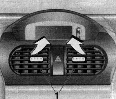
18.1. Rotary deflectors of the nozzles of the central air ducts of the upper level |
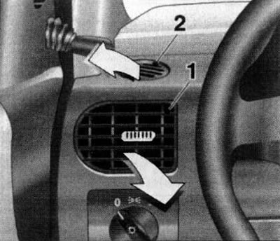
18.2. Upper level air duct side nozzle deflectors: rotating - (1), fixed - (2) |
Air is supplied to the vehicle interior in three main directions:
- To the front level of the driver, front passenger and to blow air on the side windows (central and side deflectors of the instrument panel;
- For windshield blowing (front instrument panel deflectors);
- Into the footwells of the front seats (lower air ducts).
The design of the louvered deflectors of the outlet nozzles of the front level air ducts allows you to control the intensity and direction of the outgoing flows (the rotating element is the deflector grilles)The air flow direction is changed by redirecting the grilles of the rotary deflectors (central and lateral) in the desired direction using the central handle located on the blinds of the corresponding deflector.
HVAC control panel
The HVAC control panel assembly is located in the lower portion of the instrument panel console section (see illustration 15.1).
Depending on the configuration, the car is equipped with a system with manual adjustment of operating modes, or a system with the function of automatic regulation of the air temperature in the cabin (climate control).
The HVAC, heating and air conditioning control unit consists of three rotary knobs and several pushbutton switches (depending on the configuration).
HVAC system with manual adjustment
The HVAC control panel with manual adjustment is shown in Illustration 18.3. On models without an A/C system, the buttons for activating the air conditioner and the air circulation mode (see below) are not available.
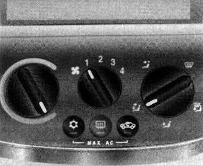
18.3. HVAC Control Panel with Manual Setting (with air conditioning)
Activation/deactivation of the system and regulation of the air flow intensity
Rotary fan speed switch (see illustration 18.3) located in the center of the HVAC control panel. To activate the system, move the switch out of the
 . Returning the regulator to this position allows you to turn off the system.
Note: When the fan is off, almost no outside air enters the vehicle interior even while driving, and ventilation of the interior is difficult.
The fan speed mode is selected by moving the switch to the appropriate position, from minimum (position 1) up to maximum (position 4).
Selecting a temperature mode
The temperature mode is selected using the rotary knob located on the left side of the control panel (see illustration 18.3). When turning the handle in the direction of the red sector of the scale, the supply of heated air will increase; when turning it in the blue sector, the supply of cold air will increase.
Selecting the direction of air flow distribution
The direction of air flow distribution is selected using the rotary switch located on the right side of the system control panel (see illustration 18.3), and provides the following options:
 Air supply to the windshield and front side windows;
 Air supply to the windshield, front side windows and footwells;
 Supplying air to the footwells and the vehicle interior;
 Air supply to the face level and footwells;
 Air supply to the facial level.
Air circulation mode (with appropriate equipment)
The air circulation mode is activated using the switch button
 on the control panel, - the control LED built into the button should light up. In this mode, the supply of fresh air is turned off, which prevents exhaust gases, unpleasant odors, dust, and plant pollen, which causes allergic reactions, from entering the passenger compartment.
Note: Long-term use of the recirculation mode leads to fogging of the windows and increased air staleness, so it is recommended to activate this mode only if really necessary and for a relatively short time. As soon as the need for interior insulation disappears, the supply of fresh air should be resumed.
Pressing the switch button again restores the air supply.
Note: When the rotary switch for selecting the air flow direction (see above) is set to the position
Air conditioning mode (with appropriate equipment)
The air conditioner operates in conjunction with the interior heating and ventilation system. In addition, the air conditioner is used to pre-dry the air. This mode is only available when the engine is running.
On models with the corresponding configuration, the K/V is activated by pressing a button
 - the LED built into the button should light up. Deactivation occurs when the button is pressed again.
Note: When the outside temperature is low, the air conditioner will automatically turn off.
To cool the air in the cabin faster, you can temporarily activate the circulation mode (see above). If there is no longer a need for cooling and drying the air, turn off the air conditioner to save fuel.
Exploitation techniques
This section provides methods for setting up the basic operating modes of a manual HVAC system.
Ventilation
Use the right rotary switch to select one of three positions for the desired air distribution direction:
, or .
Set the required temperature using the left rotary control.
Activate the system fan with the central rotary switch in the desired air flow intensity mode (from 1 to 4) - the interior will be blown by the air flow passing through the heat exchanger or bypassing it (depending on the position of the left regulator).
Heating
Note: The heating power depends on the coolant temperature and therefore reaches its maximum value only when the engine is warm.
To quickly warm up the interior:
- Select the desired air flow distribution direction;
- Turn the left knob all the way to the red section of the scale;
- Set the central rotary switch to position 3.
Heating of the lower space of the passenger compartment
Set the right switch to position
and turn the left control knob to the red sector of the scale, then activate the fan with the required air flow intensity. This mode is used to evenly heat the entire interior.
Removal condensation from glass
To quickly remove condensation, frost or ice from the windshield/front side windows, set the right switch to the position
, turn the left regulator to the red sector until it stops and set the air flow intensity switch to position 3 or 4 - if necessary, open the nozzles of the side deflectors and direct them to the side windows. Turn on the rear window heating (see Section 17).
To simultaneously heat the passenger compartment, set the air flow distribution switch to position
.
Air conditioning (with appropriate equipment)
Comfort mode
- Turn off the air circulation mode;
- Turn on the air conditioner;
- Set the air distribution direction switch to position or .
- Set the required temperature mode with the left rotary control;
- Activate the fan at the required air flow intensity;
- Adjust the intensity and direction of the air flow using the rotating deflectors.
If the temperature control handle is set to the middle position, then depending on the position of the right air distribution switch:
- warmer air will flow into the lower space of the cabin, and colder air will flow upwards;
- warm air will flow through the side deflectors, and cooler air through the central ones.
Maximum cooling
- Activate the air circulation mode;
- Turn on the air conditioner;
- Set the air distribution direction switch to position ;
- Turn the left rotary control knob until it stops in the blue sector of the scale;
- Set the central rotary switch to position 4.
- Open all air vent nozzles fully.
Removal moisture and frost from glass
- Turn on the air conditioner;
- Set the temperature control knob to the red sector of the scale;
- Activate the fan at the required air flow intensity;
- Set the air distribution direction switch to position ;
- If necessary, open and direct the side deflectors towards the side windows;
- Activate the rear window heating (see Section 17).
(Source is on the website: OPELBOOK.ru)
The presence of a large amount of moisture in the car interior, for example, in damp weather or from wet clothes, at the first moment when this mode is activated can lead to severe fogging of the windows and deterioration of visibility, which is especially dangerous when the car is moving. To prevent this effect, you must first set the air distribution direction switch to the position for about 5-6 seconds
and only then move it into position .
HVAC system with automatic temperature control function (climate control)
General information
The design of the HVAC control panel with automatic temperature control is shown in Figure 18.4. The left rotary control sets the average temperature maintained in the vehicle interior. The right rotary control controls the air flow intensity.
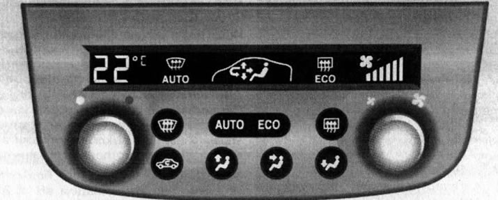
18.4. HVAC Control Panel with Automatic Adjustment
The current HVAC operating mode is indicated on a special display built into the panel above the system controls (see illustration 18.4).
The system can operate in both automatic and manual control modes. When the ignition is turned off, the settings are saved in the system memory.
Automatic system operation mode (climate control)
The AUTO mode is the basic one. This mode can be used all year round, regardless of seasonal temperature changes - the system independently regulates the intensity and direction of air supply, as well as the air flow temperature based on the user-set temperature settings, the air temperature inside the cabin and the outside atmospheric conditions. The system provides automatic compensation for changes in temperature inside the cabin under external influence, for example, sunlight.
Note: Full climate control functions are only available when the engine is running.
To activate the system in automatic mode, press the "AUTO" button located in the central part of the control panel (the corresponding indicator should appear on the display). Open the rotary deflectors fully and set the left rotary control to the average temperature that should be maintained in the passenger compartment - the set temperature value is displayed on the left side of the display directly above the control handle (see illustration 18.5). It is recommended to set the average temperature to 22°C.
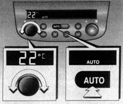
18.5. Activating HVAC in Automatic Mode (climate control)
If there is no need for cooling and drying the air, the air conditioner can be turned off by pressing the "ECO" button - the corresponding indicator will appear on the display. This automatic HVAC operation mode allows you to reduce fuel consumption, but the comfort level in the cabin may decrease.
Note: In this mode, cooling and dehumidification of incoming air is not performed, this may lead to fogging of the glass. In addition, when the outside air temperature rises, the system may malfunction.
The system is deactivated by pressing the AUTO button again.
Temperature control
Left rotary control (see illustration 18.4) the temperature mode selection sets the average temperature that should be maintained in the car interior. When you turn the knob, the set temperature value appears in the corresponding display field. The temperature value can be set between 16°C and 28°C. Under normal conditions, it is recommended to set the knob to 22°C. In automatic mode, when the average temperature value changes within the specified limits, the temperature in the interior will change gradually.
To quickly change the temperature, move the rotary control beyond the specified values. When setting the temperature below 16°C, the display will show "Lo" - the system will operate in maximum cooling mode without temperature control. When setting the temperature above 28°C, the display will show "Hi" - the system will operate in maximum heating mode without temperature control.
Windshield defroster
If necessary, for example, to quickly clear the windshield from snow, ice and condensation before starting the car, you can quickly activate the windshield defroster mode by pressing the button on the HVAC control panel
- the corresponding indicator should appear in the display field. The system automatically switches to maximum performance of the heater and fan, and the entire flow of air supplied to the passenger compartment is redirected to blowing the windshield and side windows. If necessary, the intensity of the air flow can be adjusted using the right regulator.
To deactivate this function, press the same button again or the "AUTO" button to switch to automatic mode.
Heated rear window/external rear view mirrors
The rear window heating element, and on models with the corresponding configuration, the outside rear-view mirrors, are activated using the button
 on the system control panel, - the corresponding indicator should appear in the display field (see also Section 17).
Activating/deactivating the system and adjusting the air flow intensity manually
Manual regulation of the air flow intensity is carried out by turning the right regulator. When turning the regulator, the indication of the selected air flow intensity mode is displayed on the right side of the display field directly above the regulator handle (see illustration 18.6).
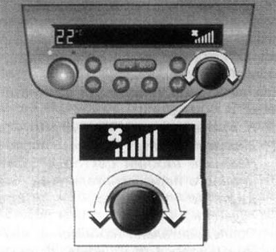
18.6. Adjusting the air flow intensity in manual mode
When the regulator is set to the extreme (all the way) left position, the system will be deactivated - the corresponding indication in the display field should go out.
To return to automatic mode, press the "AUTO" button - the air flow intensity will be selected automatically.
Selecting the direction of air flow distribution
For manual control of air flow direction selection, 3 push-button switches are provided at the bottom of the HVAC control panel (see illustration 18.7).
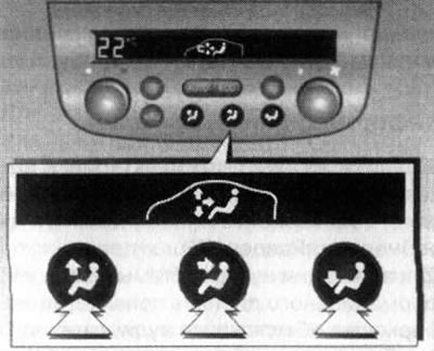
18.7. Push-button switches for manual selection of air flow direction
The following options are available:
 Air supply to the windshield and front side windows;
- Air supply to the facial level;
- Supplying air to the footwells and the vehicle interior.
One or more buttons can be pressed simultaneously - the corresponding indicator should appear in the display field.
To return to automatic mode, press the "AUTO" button - the direction of air flow distribution will be selected automatically.
Air circulation mode
The circulation mode prevents exhaust gases, unpleasant odors, dust, and plant pollen, which causes allergic reactions, from entering the passenger compartment.
Attention: As soon as the need for interior insulation no longer exists, the supply of fresh air must be resumed!
The air circulation mode is activated using the switch button
 on the control panel, - an indicator in the form of a curved arrow should appear in the display field.
Note: Long-term use of the circulation mode leads to fogging of the windows and increased air tightness, so it is recommended to activate this mode only when really necessary and for a relatively short time.
Pressing the switch button again restores the air supply.
Use of residual engine heat/air conditioning cold
Heating/cooling of the passenger compartment may continue for some time after the engine has been switched off (for example, when waiting at a railroad crossing) by using accumulated residual heat/cold. The mode is activated with the ignition off by pressing the "AUTO" button (see illustration 18.5) on the control panel, - the corresponding indicator should appear in the display field. The average temperature value is set using the left rotary switch, and the intensity and direction of air supply are adjusted automatically (usually the minimum fan speed is selected). The duration of system operation depends on the selected temperature settings and the initial temperature of the engine coolant.
The mode is switched off by pressing the "AUTO" button again or automatically by the timer signal, as well as when the battery charge level noticeably decreases.
Additional information on the HVAC system
When the air conditioner or heater is operating, the interior windows must be closed. In order for the air temperature in the car to reach the set temperature faster, it is recommended to use the air circulation mode at the initial stage of the system operation, when it is turned on.
Attention: As soon as the temperature reaches the set parameters, do not forget to turn off the circulation mode!
In hot sunny weather, after a long parking of the car in the sun, it is recommended to drive with the windows open for the first 2-3 minutes of driving and ventilate the interior for faster air cooling with the air conditioner. The operation of the air conditioning system in hot weather can lead to the formation of condensation, the removal of which can lead to the appearance of moisture streaks under the parked car, which should not cause concern.
Before driving, clear the air intake grille of snow, dirt and fallen leaves. To quickly clear the glass from ice and fogging, turn on the heater fan at full power.
To maintain the components of the A/C refrigeration system in good working order, run the compressor for a few minutes at least once a month, even if there is no need for air conditioning.
Note: On models equipped with climate control, this procedure is performed automatically while driving, however, at low outside temperatures, when the air conditioner is not activated, the driver must turn on the system as a preventive measure.
Visitor comments