
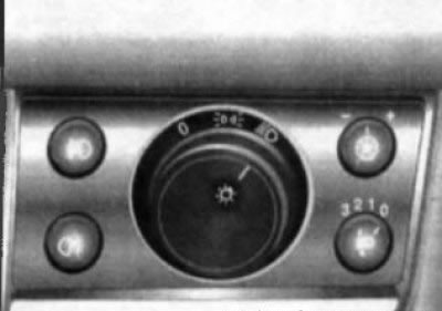
17.6 Switch panel for exterior lighting/instrument cluster illumination
- the rotary switch of modes of functioning of external lighting;
- instrument lighting brightness control (potentiometer);
- headlight optical axes direction control;
- fog light switch;
- rear fog light switch.
The slots that are not occupied by the installation of the corresponding control element are closed with decorative plugs.
Rotary switch for outdoor lighting modes
The rotary switch is located in the center of the switch panel (see illustration 17.6) and can be installed in one of 3 positions:
- ABOUT - In this switch position, all outdoor lights are off.
 When the rotary switch handle is moved to this position, the front and rear position lights, as well as the license plate light, turn on.
 When the rotary switch handle is moved to this position, the dipped headlights are switched on in addition to the previously activated running lights.
When the vehicle is equipped with a daytime running light system, even if the rotary switch is set to «ABOUT», the dipped beam will be activated automatically when the ignition is turned on. In this case, the instrument lighting remains off.
Instrument illumination brightness control (potentiometer)
The illumination of the instruments is activated when the external lighting devices are switched on. The brightness of the backlight can be adjusted using a potentiometer whose rotary knob
For adjustment, it is necessary to release by pressing the rotary knob of the regulator from the seat. Then turn the knob to the right/left as far as it will go and, holding it in this position, achieve the desired backlight brightness: to the right - increase the brightness, to the left - decrease the brightness. At the end of the adjustment, push the handle into the seat until it locks into place.
Fog light switch
When equipped, the fog light switch
Rear fog light switch
if equipped, the rear fog light switch is integrated in the lower left corner of the switch panel (see illustration 17.6).
The lights are activated when the switch is pressed, if the ignition and exterior lighting of the car are turned on, the corresponding indicator on the instrument cluster should light up (see Section 16). Pressing the same button again will deactivate the fog lamps - the indicator on the instrument cluster goes out.
Note: When towing a trailer, the rear fog lights turn off.
Hood latch release lever
The hood release lever is located under the instrument panel to the left of the steering column (see illustration 15.1). See Section 4 for a description of the hood release procedure.
Hazard switch
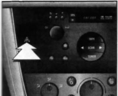
17.9 Alarm switch
The alarm is activated using a push-button switch mounted in the left switch panel of the console section of the instrument panel (see illustrations 15.1 and 17.9). The button is marked with an icon depicting two triangles inscribed in each other. To make it easier to find the switch, when the ignition is turned on, the red field of the button is highlighted. Pressing the alarm button leads to the simultaneous operation of all four direction indicators (and their indicator lights on the vehicle's instrument cluster). The alarm is designed to warn other road users about the forced stop of the car and is also used in other dangerous situations provided for by traffic rules. To turn off the alarm, press the switch button again.
Sport mode switch (SPORT)
Models of recent years of production can be equipped with a sport driving mode system (see Section 25). Sport mode activation button «SPORT» (with appropriate equipment) built into the right switch panel of the console section of the instrument panel (see illustration 17.12a).
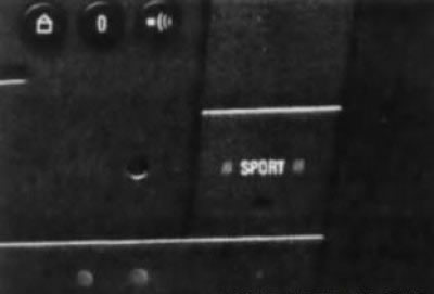
17.12a Sport mode switch
For more information, contact an authorized Opel dealer.
Anti-skid switch (EZR) /anti slip (TS) systems
17.12b Anti-skid switch (E8P) /anti slip (TS) systems
On eligible models, the switch button for the respective system is integrated into the right switch panel of the console section of the instrument panel (see illustration 17.12b).
The ESP / TC system is activated automatically when the ignition is switched on; the functional readiness of the system is confirmed by an indicator on the instrument panel (see Section 16). If necessary, this system can be turned off forcibly, for which you need to press the switch button - the indicator built into the instrument panel should light up in a constant mode. Disabling the system is possible only when driving at speeds below 60 km/h The system is activated after switching off by pressing the switch button again or automatically when the ignition is turned on again.
Seat heating switches
On models of the corresponding configuration, the cushions of the front and rear side seats are equipped with built-in heating elements, which are activated from individual switches. Front seat switches integrated into console section of instrument panel (see illustration 17.13a), and the rear side seat switches are located on the rear end panel of the center console (see illustration 17.13b).
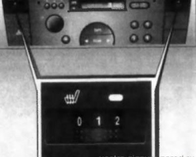
17.13а Switch buttons and roller controls for electric heating of front seat cushions
17.13b Buttons for switches for electric heating of rear side seat cushions
To activate the electric heating, it is necessary to press the button of the corresponding switch - the LED built into the switch button should light up. For the front seats, the function of adjusting the intensity of heating is provided - turn the roller regulator to the required position.
Attention! People with hypersensitivity of the skin are not recommended to use heating for a long time when activating heating elements at the highest intensity!
The operation of the electric heater of each seat is controlled by a temperature-sensitive sensor-switch, which automatically turns on and off the corresponding heating element, maintaining the set temperature. The electric heating system starts to function only when the ignition is on.
Attention! Do not turn on the electric heaters for a long time, and also if there is no passenger on the seat! Never cover the seats with any heat-insulating coverings (blankets, cushions, slipcovers, etc.), - this can lead to overheating of heating elements! Do not put hard and heavy objects on the seats, do not pierce the seat cushions with pins or similar objects, as this may lead to failure of the heating elements.
Theft alarm switch
If equipped, the switch is mounted in the right panel of switches of the console section of the instrument panel under the electric heating switch of the front passenger seat (see illustration 8.3). For more information, see Section 8 of this Chapter.
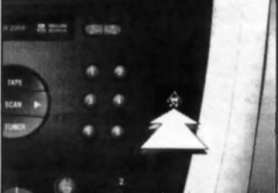
Rear window sunshade power switch
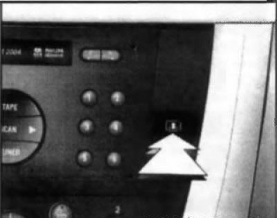
17.14 Rear window sunblind switch
If equipped, the rear window can be covered with a sunblind to reduce sun exposure. To raise the curtain, press the switch button (see illustration 17.14), located on the right panel of the console section of the instrument panel. To lower the blind, press the same button again.
Control unit for the functioning of ventilation, heating and air conditioning systems
Control unit for the functioning of ventilation / heating / air conditioning systems (HVAC) is placed at the bottom of the console section of the instrument panel. Detailed information on the block describing the principles of systems management is given in Part D of this Chapter. For the purposes of this subsection, only the pushbutton switch is considered (see illustration 17.15) activation of heated rear window/door mirrors integrated in the panel of the HVAC control unit.
Heated rear window/door mirror button
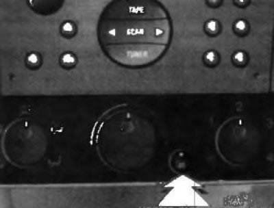
17.15 Button switch for heated rear window/door mirrors
Electric heating is activated by pressing the
The filamentous mesh of the heating element of the heater is glued to the inner surface of the rear window and requires care in handling - try not to damage the mesh when wiping the glass (wiping should be done only along the heater filaments).
Controls located on the center console
Lever of the selector AT/gear shifting manual transmission
The AT selector/gearshift lever has a floor-mounted design and is placed on the center console panel. Features of driving a car with various configuration options are described in Part E.
Parking brake lever
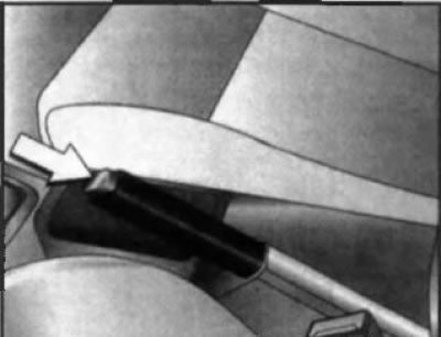
17.16 Handbrake lever
The parking brake lever is located between the front seats, on the center console (see illustration 17.16). To cock the parking brake, without pressing the lock button on the end part, pull the lever up towards you (lever locking is automatic), - the corresponding control lamp on the instrument cluster must be activated (see Section 16). To release the parking brake, pull the lever up slightly, press the release button on the end of the lever handle, then push it down. To facilitate lever movement, it is recommended to hold the vehicle with the foot brake pedal.
Attention! Do not forget to release the parking brake before driving off - make sure that the indicator lamp built into the instrument cluster is turned off!
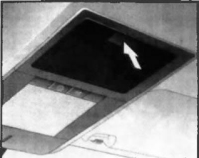
Overhead console controls
Switches for selecting the operating mode of interior lighting
Interior lighting is produced when the lamps mounted in the ceiling panels of the interior are activated (see illustrations 17.17, 17.18).
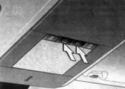
17.17 Switches of a forward lamp of illumination of salon
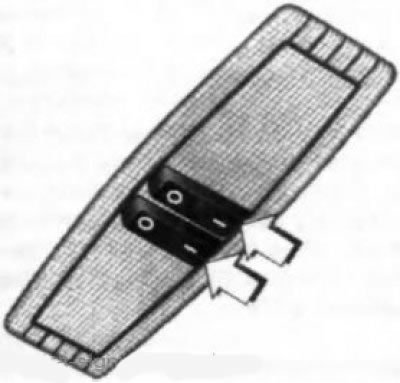
17.18 Rear general lighting/reading lights
The front lamp is activated when any of the side doors of the car is opened and goes out after a short delay after the door is closed. To activate the lamp with the doors closed, you must press the switch button
Switches for directional individual lamps of the front seats
With the appropriate configuration, directional individual lamps for the front seats are mounted in the front interior lighting (see above). Lights are activated when the ignition is on by pressing the
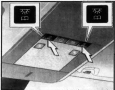
17.19 Switches for individual lamps in front seats Switches for directional individual lamps in rear seats
When equipped, rear reading lights (see illustration 17.18) activated separately (right and left) when the ignition is on, when the corresponding switch is moved to the position «I». To deactivate, move the switch to the position «ABOUT».
Battery discharge protection
On models with the appropriate equipment, interior lighting, reading lamps, luggage compartment and main glove compartment lighting are automatically switched off when the ignition is switched off 20 minutes regardless of the position of the switches.
Attention! Do not leave the lighting devices switched on for a long time with the engine turned off!
Additional illumination
To ensure the convenience of using some of the controls and equipment of the car in low light conditions, interior lighting is provided. The illumination of the interior volume of the luggage compartment and the main glove box is activated when the tailgate/glove box lid is opened. If equipped, the backlight can be activated:
- Make-up mirror in sun visors - when opening the mirror cover;
- Illumination of the cigarette lighter and ashtray - with the ignition on.
Sunblind
In both the closed and open positions, the top sunroof can be covered with a sunblind. The curtain is moved manually. When opening the upper sunroof, the sunblind is removed automatically - after closing the sunroof, it can only be returned to its original position manually.
Rear side window sunblinds
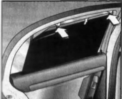
17.27 Closing the blind of the rear side window
If equipped, the rear side windows can be covered with sunblinds to reduce sun exposure. Pull out the appropriate shade using the handle located in the center of the top edge of the shade and secure the shade in the top holders (see illustration 17.27).
Storage boxes and pockets
Attention! Before driving off, all storage boxes must be closed!
Main storage box
The main glove box is located on the right side of the instrument panel and is equipped with a hinged lid. There is a pencil holder at the front of the open lid.
On corresponding models (equipped with air conditioning) the function of cooling the main glove box is provided. Cooled air enters through a nozzle located on the side wall of the box. If there is no need to cool the front glove box, move the knob down (see illustration 17.31).
17.31 Regulator for supplying air to the main storage box
Storage box in the front armrest
If equipped, a stowage box is integrated into the front seat armrest - see Section 12.
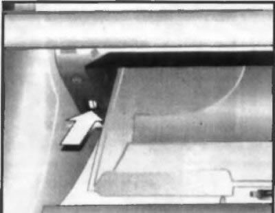
Overhead console storage boxes
If equipped, the storage box can be integrated into the overhead console next to the front seat light (see illustration 17.32). To open the box, press its lid in the marked place. When the lid is closed, the latch locks automatically.
17.32 Overhead console storage box
On Signum models, the full height ceiling panel can be equipped with a complete storage system (see illustration 17.33). These stowage boxes are designed to store books, document folders, eyeglass cases and other small items that may be needed on a trip and should be at hand. The maximum load capacity of the overhead console storage boxes is 0.4 kg.
Luggage compartment stowage boxes
Left and right sides of the luggage compartment are equipped with storage boxes. Depending on the type of body, the boxes can be of various shapes and sizes. The storage box on the left side panel is used to store a first aid kit, and on some models to store a warning triangle (see below). To open the lid of the glove box, it is necessary to press the upper latch (clamps) and flip the lid down (see illustration 17.34).
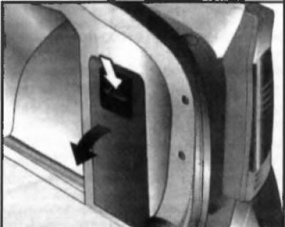
17.34 Opening the glove box in the luggage compartment
Pockets
Door pockets are designed to store small items and items that should be at hand during the trip.
Attention! Do not overload pockets, do not put excessively heavy objects in them!
In some versions, there may be two additional padded pockets on the back of the front seat backrests or mesh pockets, these pockets should not be used to store hard objects.
Cup holders
Attention! The driver should not drink drinks and use cup holders while the car is moving - all the driver's attention should be focused on driving and ensuring traffic safety! Avoid sudden acceleration and deceleration when containers with drinks are placed in the cup holders - if a hot drink is spilled, the driver or passengers may be burned!
Front cup holders
Front cup holders (with appropriate equipment) located on the center console, between the front seats. When the cup holders are not in use, they are closed with a lid (see illustration 17.35).
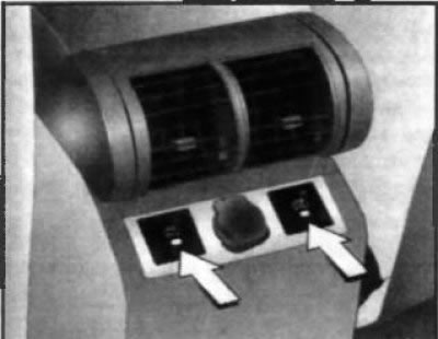
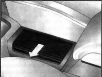
Rear cup holders
On eligible models, the rear cup holders are integrated into the center section of the rear bench seat cushion (see illustration 17.36). To use them, you must press the front edge of the cup holders - they will slide out into position for use. Don't forget to fold the cup holders when not in use - the latch is automatically locked.
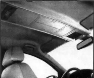
17.33 Overhead console storage boxes on Signum models (with appropriate equipment)
17.35 Opening the cover of the front cup holders
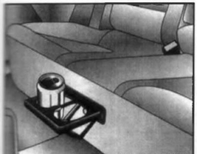
17.36 Rear cup holders
Sun visors
The sun visors protect the eyes of the driver/front passenger from direct sunlight. The visors are mounted on brackets of a swivel design, which, if necessary, can be turned parallel to the side windows of the car (first release the bracket from the retainer). Depending on the configuration, a pocket for storing documents or a built-in makeup mirror can be provided on the back of the visor (on some models, the mirror can be equipped with a light).
Visitor comments