
Warning and instrument panel lights
Turn the appropriate bulb socket counterclockwise and remove it from the circuit board on the back of the dashboard (pic. 12.24).
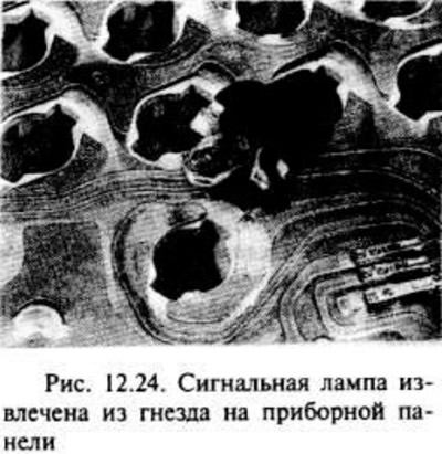
Lamps are mounted in a single assembly with a cartridge and are replaced as one piece.
Installation is carried out in the reverse order of removal.
Voltage regulator
Remove the screw from the back of the dashboard, then remove the voltage regulator by unplugging the pins on the PCB (pic. 12.25).
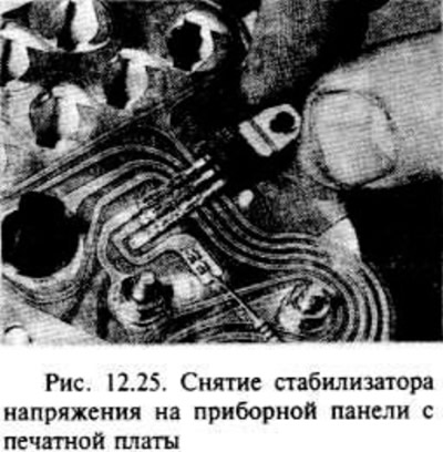
Installation is carried out in the reverse order of removal; take care not to damage the contacts of the voltage regulator with the printed circuit board.
Temperature and fuel gauges - models without a tachometer
Remove the odometer dowel pin (trip counter) from the front of the instrument panel.
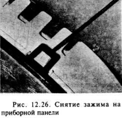
Release the two clips at the top of the panel and remove the panel shroud (pic. 12.26).
Loosen the two screws and remove the respective instrument through the front side of the instrument panel.
Installation is carried out in the reverse order of removal.
Speedometer
After removing the odometer and releasing the clips at the top of the dashboard, remove the four screws from the back of the dashboard and remove the speedometer from the front of the dashboard.
Installation is carried out in the reverse order of removal.
Printed circuit board
Remove all light bulbs and appliances and the voltage regulator as described earlier in this section.
Carefully remove the circuit board from the dashboard.
Installation is carried out in the reverse order of removal, however, make sure that the printed circuit board is installed correctly on the back of the instrument panel.
Visitor comments