
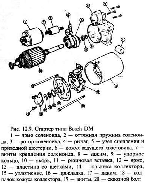
Starter type Bosch DM
After removing the motor from the vehicle and cleaning it, clamp it in a soft-seated vise.
Loosen the nuts at the through bolts and remove the bracket, if installed.
Remove the nut and washer securing the winding wire to the solenoid stud and separate the wire from the stud.
Remove the two screws securing the manifold end cap cap, then remove the cap and rubber seal.
Remove dirt from the rotor shaft, then remove the C-clip and gaskets from the ends of the shaft.
Loosen the two through bolts and remove the manifold cover.
Release the brush holders along with the brushes by pushing the brush holders towards the commutator and pressing them away from the brush plate. Remove the plate (pic. 12.9).
Detach the shank guard and armature from the yoke by gently tapping with a soft-shelled hammer.
Remove the three screws and pull out the solenoid yoke, then disconnect the solenoid rotor from the arm and remove the rotor.
Remove the rubber insert from the drive shaft housing, then remove the arm pin lock nut and remove the pivot pin from the housing.
Remove the rotor assembly along with the lever from the casing.
Disconnect the lever from the gear flange.
To remove the drive gear from the armature shaft, remove the thrust washer from the shaft with a suitable tube punch to release the C-clip. After removing the clamp, pull the thrust collar and drive gear off the shaft.
Inspect parts and replace defective parts if necessary.
If the brushes are worn almost to the limit, replace the entire set.
The surface of the collector contacts must be clean without burn points. Where required, polish the contact surfaces with fine glass wool (just not sandpaper) and wipe with a cloth soaked in gasoline.
Replace manifold end cap and bushings (self-lubricating type) drive shaft cover, which must be kept in a clean engine room for at least 20 minutes.
Reliable testing of the armature, collector, field windings and insulation requires the use of special equipment. If the motor is not running and the checks have not cleared up any problems, a circuit or insulation fault may be suspected. In this case, the unit must be replaced.
Begin assembly by fitting the drive gear and thrust ring onto the armature shaft. Install the C-ring in place, and then use a puller to install the snap ring.
Connect the lever to the drive gear flange, then install the armature and drive lever assembly into the housing.
Establish an axis of a driving lever and fix it with a stopper. Install the rubber insert into the casing.
Apply some grease (lithium based) onto the hook of the solenoid, then install it over the drive arm in the housing. Check that the return spring is in the correct position, then put the yoke on the anchor.
Install the brush plate over the end of the shaft, assemble the brush holders and springs.
Replace the manifold end cap and install the through bolts.
Install the rotor on the bearings.
Install sufficient shims on the end of the rotor shaft to eliminate longitudinal play.
Install the rubber seal on the manifold end cap, then apply some grease (lithium based) onto the end of the shaft, secure the end cover cap with two screws.
Connect the field wire to the solenoid stud and secure it with a nut and washer.
Install the bracket on the through bolts and secure it with two nuts.
Visitor comments