
OpelBook.ru
Cars AvtoVAZ Cars Mitsubishi Cars BMW Cars Mercedes Cars Nissan Cars Toyota Cars Chevrolet
English Русский
Български
Беларускі
Український
Српски
Hrvatski
Română
Polski
Slovenský
Magyar
 |  Sitemap  |  Contacts  |    


Main Astra Corsa Insignia Kadett Omega Vectra Zafira Others Articles
Astra F (1991-1998, petrol) Astra G (1998-2004, petrol) Astra G (1998-2004) Astra H (2004-2009) Astra J (2009-2015, petrol)
  • Main
  • Astra
  • Astra F
  • Electrical equipment
  • Equipment and devices
  • Stabilizer and brushes — inspection and replacement

Stabilizer and brushes — inspection and replacement (Opel Astra F)

            0

Contents: Delco-Remy type generator (Fig. 12.3) ⬇ Bosch type current generator (Fig.…⬇
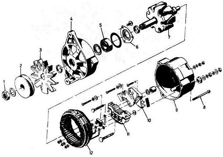
Delco-Remy type generator (Fig. 12.3)


Fig. 12.3. Delco-Remy type current generator:

Fig. 12.3. Delco-Remy type current generator:

1 - pulley nut; 2 - pulley; 3 - fan; 4 - drive shaft casing; 5 - bearing; 6 - bearing support; 7 - rotor; 8 - through bolt; 9 - contact track casing; 10 - brush holder/voltage stabilizer. 11 - diode block; 12 - stator


The brush holder and voltage regulator are combined into one unit. To access the assembly, the generator must be partially disassembled as shown below. If the voltage regulator is faulty, the entire unit must be replaced.

Remove the generator as described above.

Draw a line across the drive shaft end housing and the slip ring end housing to ensure proper alignment during assembly.

Remove the three through bolts and separate the shaft housing from the slip ring housing and stator.

Check the condition of the contact rings and, if necessary, remove dirt with a rag or very fine glass sandpaper.

After removing the three nuts and washers securing the stator wires, remove the stator assembly (Fig. 12.5).
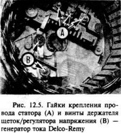


After removing the three nuts and washers securing the stator wires, remove the stator assembly…


Remove the screw and take out the diode block.

After removing the two screws securing the brush holder and voltage stabilizer to the contact track housing, remove the brush holder assembly.

Check that the brushes move freely in their guides and that the brush length is within the limits specified in the technical specifications.

To install new brushes, unsolder the ends of the holder connections and solder new wires.

Check that the new brushes move freely in the guides.

Before installing the brush holder assembly, push the brushes aside using a suitable tool.

Install the diode block and stator assembly.

Install the generator as described in the previous section.

Bosch type current generator (Fig. 12.4)
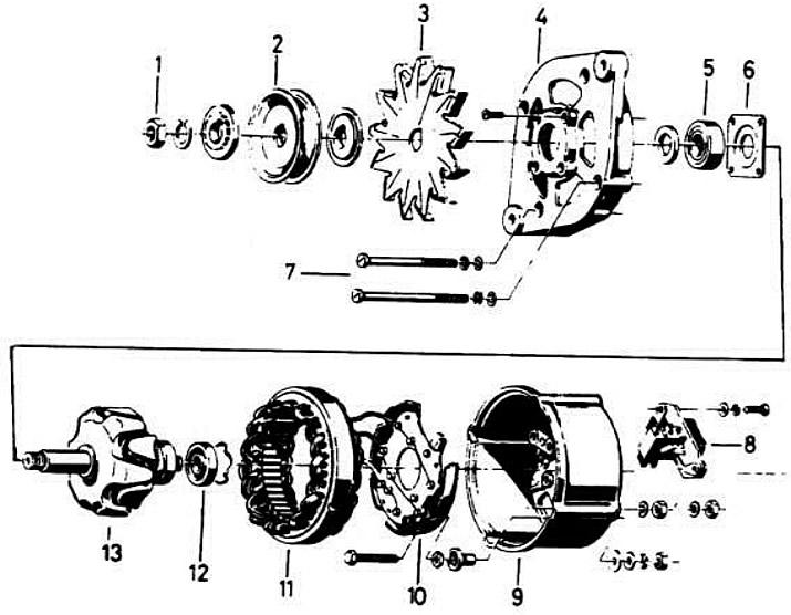


Fig. 12.4. Bosch type current generator:

Fig. 12.4. Bosch type current generator:

1 - pulley nut; 2 - pulley; 3 - fan; 4 - drive shaft casing; 5 - bearing; 6 - bearing support; 7 - through screws; 8 - brush holder/voltage stabilizer; 9 - contact track casing; 10 - stator cover; 11 - stator; 12 - bearing; 13 - rotor


The brush holder and voltage stabilizer are combined in one unit, which is secured with bolts at the end of the generator. If the voltage stabilizer is faulty, the entire assembly must be replaced.

Disconnect the air lines from the air cleaner and air box or throttle body and where necessary to provide adequate access.

Disconnect the negative battery terminal.

Remove the two screws and take out the brush holder/voltage stabilizer assembly (Fig. 12.6).
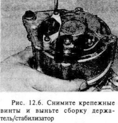
Remove the two screws and take out the brush holder/voltage stabilizer assembly (Fig. 12.6).


Make sure that the brushes move freely in the guides and that the length of the brushes is within the limits specified in the technical specifications (Fig. 12.7).
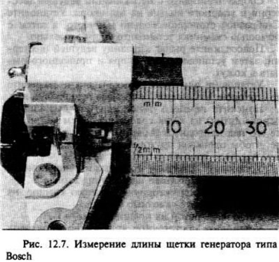
Make sure that the brushes move freely in the guides and that the length of the brushes is within…


If there is any doubt about the condition of the brushes, it is best to replace them as indicated below.


Clamp the brush wire with pliers and unsolder it. Remove the brush. Do the same with the other brushes.

After installing the new springs on the brush holder, insert the new brushes and make sure they move freely in the guides. If they stick, lightly polish them with a velvet file or fine glass paper.

Solder the ends of the brush wires to the brush holder.

Check the condition of the contact rings and, if necessary, remove dirt from them with a rag or very fine glass sandpaper.

Install the brush holder/voltage stabilizer assembly and tighten the screws.

Install the generator as described above.

Connect the negative battery terminal.

Install air ducts.


This article is available at russian, bulgarian, belarusian, ukrainian, serbian, croatian, romanian, polish, slovak, hungarian
Checking the article: Trifonova Emilia

Share information:

Previous articles
Opel Astra F: Equipment and devices
Next articles

Current generator — removal and installation
Generator Drive Belt — Removal, Installation and Tensioning
Charging system — check
Battery — Removal and Installation
Battery — Checking and Charging
Finding defects in electrical equipment — general information
Starting system — check
Starter motor — removal and installation
Starter motor — repair
Fuse Box — Removal and Installation
Fuses and relays — checking and removing
Switches — removal and installation


See similar ones from other Opel car manuals:
▶ Checking the condition and replacing the brushes Opel Corsa B (1993-2000)
▶ Replacing the front suspension stabilizer bar struts Opel Insignia A (2008-2017)
▶ Removal and installation the stabilizer Opel Kadett D (1979-1984)
▶ Generator brushes and voltage regulator — removal and… Opel Omega A (1986-1993)
▶ Generator brushes — removal, inspection and installation Opel Vectra A (1988-1995, petrol)
Link to this page in different formats

Visitor comments


No comments yet


How much will 12 + 47 =


Astra J (2009-2015, petrol) 
  • General information
  • Vehicle device
  • User manual
  • Faults en route
  • Maintenance
  • Power unit
  • Engine repair
  • Cooling and lubrication system
  • Engine power system
  • Exhaust system
  • Transmission
  • Clutch
  • Car gearbox
  • Drive shafts
  • Chassis
  • Front suspension
  • Rear suspension
  • Steering
  • Brake system
  • Wheels and tires
  • Body
  • Exterior
  • Interior
  • Doors and windows
  • Body Care
  • Heating and air conditioning
  • Security systems
  • Electrical equipment
  • Equipment and devices
  • Lighting and signaling
  • Power devices
  • Electrical circuits
Astra H (2004-2009) 
  • General information
  • Introduction to the guide
  • Troubleshooting
  • User manual
  • Maintenance
  • Power unit
  • Engine repair
  • Cooling and heating
  • Power and exhaust system
  • Ignition system
  • Launch and charge system
  • Transmission
  • Mechanical gearbox
  • Automatic gearbox
  • Drive shafts
  • Chassis
  • Brake system
  • Car suspension
  • Steering
  • Body
  • Interior
  • Exterior
  • Electrical equipment
  • Equipment and devices
  • Electrical circuits
Astra G (1998-2004) 
  • General information
  • Introduction to manual
  • User manual
  • Maintenance
  • Power unit
  • SOHC gasoline engines
  • DOHC gasoline engines
  • Diesel engines 1.7 and 2.0
  • Engine repair
  • Cooling system
  • Supply system
  • Injection system (gasoline)
  • Injection system (diesel)
  • Exhaust system
  • Charge and launch system
  • Ignition system (gasoline)
  • Preheat system (diesel)
  • Transmission
  • Manual gearbox
  • Automatic gearbox
  • Clutch
  • Drive shafts
  • Chassis
  • Brake system
  • Wheel suspension
  • Steering
  • Body
  • Exterior
  • Interior
  • Doors and windows
  • Ventilation and heating
  • Electrical equipment
  • Equipment and devices
  • Electrical circuits
Astra G (1998-2004, petrol) 
  • General information
  • User manual
  • Car care
  • Maintenance
  • Power unit
  • Single shaft engines
  • Twin shaft engines
  • Engine repair
  • Cooling and heating
  • Fuel and exhaust systems
  • Starting and charging system
  • Ignition system
  • Transmission
  • Clutch
  • Mechanical gearbox
  • Automatic gearbox
  • Drive shafts
  • Chassis
  • Brake system
  • Car suspension
  • Steering
  • Body
  • Interior
  • Exterior
  • Electrical equipment
  • Equipment and devices
  • Wiring diagrams Opel Astra
  • Wiring diagrams Opel Zafira
Astra F (1991-1998, petrol) 
  • General information
  • Maintenance
  • Power unit
  • Engine in car
  • Engine removed
  • Cooling system
  • Heating and ventilation
  • Fuel supply (carburetor)
  • Fuel supply (injector)
  • Emission control
  • Ignition system
  • Transmission
  • Clutch
  • Mechanical gearbox
  • Automatic gearbox
  • Drive shafts
  • Chassis
  • Brake system
  • Car suspension
  • Steering
  • Body
  • Exterior
  • Interior
  • Electrical equipment
  • Equipment and devices
  • Electrical circuits
OpelBook.ru © 2017–2026 · Mobile version · · Sitemap: EN BG BY UA RS HR RO PL SK HU · Feedback · Site search
Astra F, petrol · Astra G, petrol · Astra G · Astra H · Astra J, petrol · Corsa B · Corsa C, petrol · Corsa C · Insignia A · Kadett D · Kadett E · Omega A · Omega B · Omega B2 · Vectra A, petrol · Vectra A · Vectra B, petrol · Vectra B · Vectra C · Zafira A, petrol · Frontera A, petrol · Frontera B · Ascona C · Vivaro A ·
We want your visit to be comfortable 🤝! We use cookies 🍪 to make that happen.