
Switch (lock) ignition
Disconnect the negative battery terminal.
Remove the covers from the steering column as directed in chapter 10.
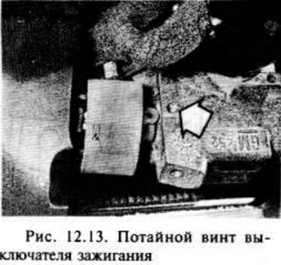
Switch (lock) ignition is fixed to the casing with two countersunk screws.
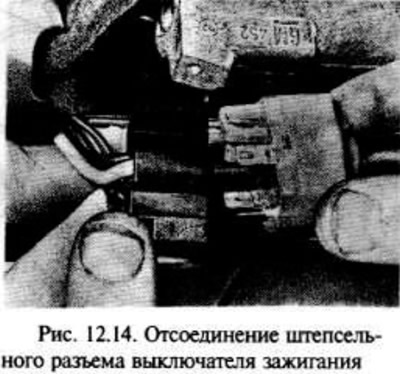
Disconnect the wiring and remove the screws to remove the switch. It is not recommended to remove the switch and the lock cylinder at the same time, as their mutual position may be disturbed (fig.12.13, 12.14).
Installation is carried out in the reverse order of removal.
Steering column switches
Carry out the operations indicated in the first and second paragraphs of this section.
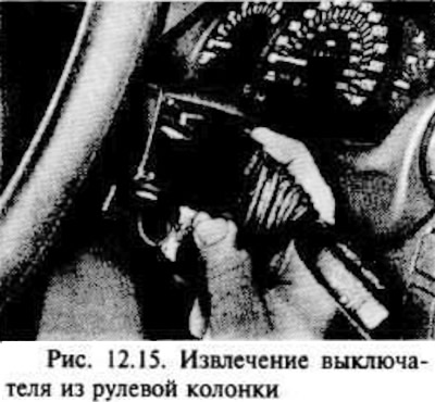
Squeeze the clips and remove the switch from the steering column (pic. 12.15).
Disconnect the switch connector (pic. 12.16).

Installation is carried out in the reverse order of removal.
Light switch
Disconnect the negative battery terminal.
Insert a small screwdriver or rod into the hole at the bottom of the switch handle to compress the latch. Remove the handle from the switch (pic. 12.17).

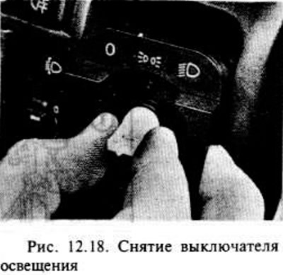
Press the switch clips that have now opened towards the switch stem, then remove it from the instrument panel and disconnect the plug (pic. 12.18).
The switch assembly cannot be disassembled, therefore, in case of failure, it is completely replaced.
Installation is carried out in the reverse order of removal.
Pushbutton switches on the instrument panel
Disconnect the negative battery terminal.
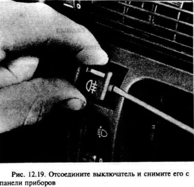
Using a screwdriver, carefully remove the switch, taking care not to damage the instrument panel (pic. 12.19).
Installation is carried out in the reverse order of removal.
Hazard switch
Disconnect the negative battery terminal.
Put the switch in position "ON" ("incl.").
Using a screwdriver, carefully pry out the switch button to release it.
Using a screwdriver, carefully pry out the switch itself.
Installation is carried out in the reverse order of removal.
Horn switch
Carefully remove the center steering wheel horn button and disconnect the wire.
If desired, the horn switch contact assembly can be pulled out of the center of the steering wheel after the steering wheel has been removed, as indicated in chapter 10.
Stop signal switch
Disconnect the negative battery terminal.
In the recess for the driver's feet, release the clips and remove the lower trim.
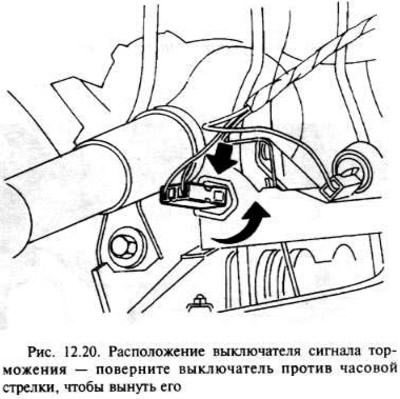
The switch is mounted on a bracket next to the steering column at the top of the brake pedal.
Disconnect the plug from the switch.
Turn the switch counterclockwise. to remove it from the bracket (pic. 12.20).
Installation is in the reverse order of removal, however, make sure that the brake lights should turn on when the brake pedal is depressed approximately 15.0-20.0 mm. The switch can only be adjusted by carefully bending the bracket, but this is not recommended.
Low Oil Pressure Warning Switch
The switch is mounted on the end face of the oil pump on the side of the intake manifold of the engine.
Disconnect the negative battery terminal.
On most models, the switch can be accessed from above, but on some models, access is best achieved by jacking up the front of the vehicle and jacking it securely under the axle, then removing the right road wheel. On models with twin cam engines, remove the access hatch from the lower engine mudguard.
Disconnect the wire from the switch.
Place a suitable container under the switch to collect any oil that will flow out when the switch is removed.
Using a suitable wrench, unscrew the switch. There may be oil leakage, so close the hole in the oil pump.
Installation is carried out in the reverse order of removal, however, after completing the check, top up the engine oil level.
Visitor comments