
OpelBook.ru
Cars AvtoVAZ Cars Mitsubishi Cars BMW Cars Mercedes Cars Nissan Cars Toyota Cars Chevrolet
English Русский
Български
Беларускі
Український
Српски
Hrvatski
Română
Polski
Slovenský
Magyar
 |  Sitemap  |  Contacts  |    


Main Astra Corsa Insignia Kadett Omega Vectra Zafira Others Articles
Frontera A (1991-1998, petrol) Frontera B (1998-2004) Ascona C (1981-1988) Vivaro A (2001-2014)
  • Main
  • Opel
  • Ascona C
  • Electrical equipment
  • Equipment and devices
  • Switches — removal and installation

Switches — removal and installation (Opel Ascona C)

            0

Contents: Heater Fan Switch ⬇ Rear window defroster switch ⬇ Emergency Flashing Light Switch ⬇ Steering Column Switches ⬇ Interior Light Switch ⬇ Rear fog light switch ⬇ Trunk Light Switch (Estate) ⬇ Electric window lift switches ⬇ External rear view mirror electric…⬇ All switches ⬇
1. Before removing any switch, be sure to disconnect the negative battery cable.

Heater Fan Switch


2. The fan switch is held in place by spring clips that should be pressed in using a knife blade inserted behind the switch socket while simultaneously pulling the switch out of the panel.

3. If you encounter difficulties pulling out the switch, you can use an alternative method of removing the switch panel after the mounting screws have been removed (see photo 21.3).
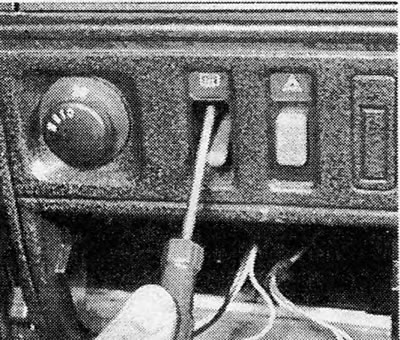
Photo 21.3 Unscrewing the mounting screw of the switch panel

Photo 21.3 Unscrewing the mounting screw of the switch panel


4. Disconnect the switch wiring plug.

Rear window defroster switch


5. This switch can be accessed by removing the panel screws and then pulling the panel out of the dashboard (see photo 21.5). Headlight switch
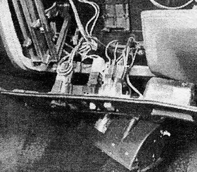
Photo 21.5 Mounting panel and switches for heater fan/rear window defroster/hazard warning lights

Photo 21.5 Mounting panel and switches for heater fan/rear window defroster/hazard warning lights


6. The spring tabs that hold the switch in place should be pressed by inserting a blade behind the switch socket and then the switch is pulled out of the panel until its wiring can be disconnected.

7. Alternatively, you can remove the entire switch panel after unscrewing the mounting screws (see photo 21.7). Removing the switch panel also provides access to the instrument panel light switch, which is installed on some models.
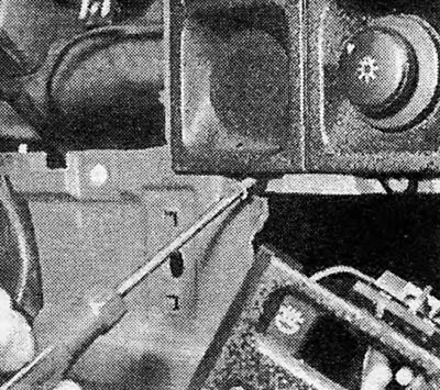

Photo 21.7 Light switch panel screw

Photo 21.7 Light switch panel screw


Emergency Flashing Light Switch


8. Access to this switch is obtained in the same way as described for the rear window heating switch.

Steering Column Switches


9. Loosen the mounting screws and remove the lower cover from the top of the steering column.

10. Remove the top cover. It should be possible to remove the column through the steering lock socket, but if this is difficult, you can first remove the lock by pressing on its plunger with a thin rod. The ignition key must be in position "1".

11. Press the retaining tabs on the switch and pull it out far enough to allow the electrical plug to be disconnected. Remove the switch (see photo 21.11 A and B).
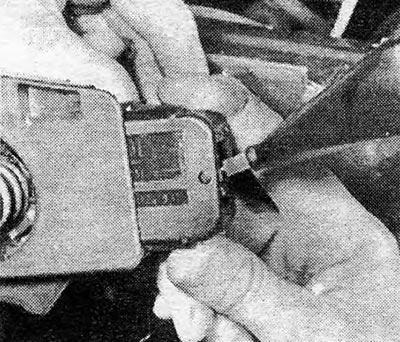


Photo 21.11A Pressing the retaining tabs of the switch on the steering column
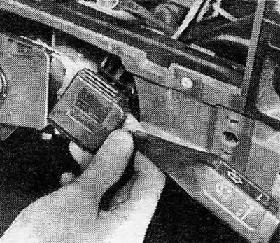
Photo 21.11A Pressing the retaining tabs of the switch on the steering column


Photo 21.11B Removing the steering column switch

Photo 21.11B Removing the steering column switch


Interior Light Switch


12. It is located in the door pillar and is of the plunger type.

13. To remove the switch, unscrew the retaining screw and pull it out of the stand (see photo 21.13).
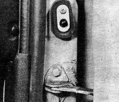
Photo 21.13 Interior light switch

Photo 21.13 Interior light switch


14. If you need to remove this switch completely, tape its wiring to the door pillar to prevent the wiring from sliding into the pillar.

15. Before installing the switch in place, lubricate its moving parts with Vaseline to prevent corrosion.

Rear fog light switch


16. Access to this switch and others adjacent to it is best obtained by unscrewing the retaining screws and pulling the entire switch panel out of the dashboard (see photo 21.16). You can get to the two fixing screws after removing the plastic decorative plate on the left.
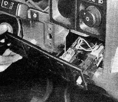
Photo 21.16 Rear fog light switch panel

Photo 21.16 Rear fog light switch panel


17. The electrical wiring plugs and switches can then be released by pressing on the tabs of their spring clips.

Trunk Light Switch (Estate)


18. Remove the rear door interior trim panel (see Chapter 11, Section 15).

19. Press the switch plunger and disconnect the wiring from the back of the switch. Press the switch housing out of the rear door (see photo 21.19).
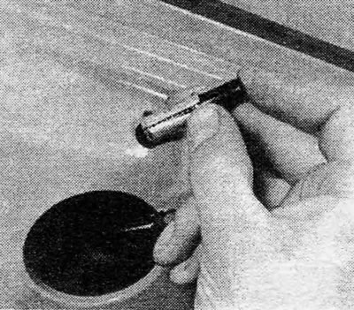
Photo 21.19 Removing the trunk light switch (Estate)

Photo 21.19 Removing the trunk light switch (Estate)


Electric window lift switches


20. If such a mechanism is installed, the switches are located on the upper part of the center console.

21. To remove them, simply pull the switch in question out of place, then lift it up so that its wiring can be disconnected (see photo 21.21A).
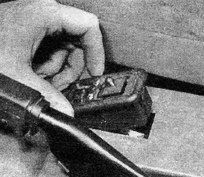
Photo 21.21A Removing the switch of the electric regulator of the position of the outside rearview…

Photo 21.21A Removing the switch of the electric regulator of the position of the outside rearview mirror
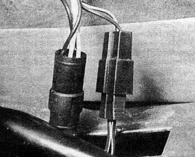

Photo 21.21B Wiring of the switch for the electric adjustment of the position of the outside…

Photo 21.21B Wiring of the switch for the electric adjustment of the position of the outside rearview mirror


External rear view mirror electric position adjuster switch


22. This switch is accessed in the same manner as described for the electric window switches.

All switches


23. Installation is carried out by performing the above steps for removal in reverse order; before installation, check that the switch functions properly. The switches, which are held in place by spring tabs, simply click into place.
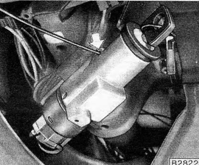


Figure 12.15. Releasing the ignition lock cylinder. The arrow indicates the position of the thin…

Figure 12.15. Releasing the ignition lock cylinder. The arrow indicates the position of the thin rod pressing on the plunger
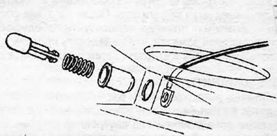

Figure 12.16. Trunk light switch - Estate
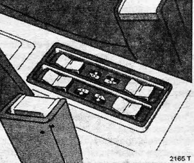
Figure 12.16. Trunk light switch - Estate


Figure 12.17. Electric window switches

Figure 12.17. Electric window switches


This article is available at russian, bulgarian, belarusian, ukrainian, serbian, croatian, romanian, polish, slovak, hungarian
Checking the article: Kornev Georgy

Share information:

Previous articles
Opel Ascona C: Equipment and devices
Next articles

Relay — location, installation
Fuses — Checking and Replacing
Service and Maintenance — Electrical System
General description
Starter Delay Switch (Automatic Transmission) — Adjustment
Sound signal(s) and switch
Watch — removal and installation
Cigarette lighter — removal and installation
Instrument panel — removal and installation
Instruments — removal and installation


See similar ones from other Opel car manuals:
▶ Cooling system switches — checking, removing and installing Opel Astra F (1991-1998, petrol)
▶ Removal and installation rear fog light (fog light) and… Opel Corsa B (1993-2000)
▶ Steering Column Combination Switches — Removal and… Opel Omega A (1986-1993)
▶ Submode switches — removal and installation Opel Vectra A (1988-1995, petrol)
▶ Steering column switches Opel Zafira A (1999-2005, petrol)
Link to this page in different formats

Visitor comments


No comments yet


How much will 36 + 29 =


Vivaro A (2001-2014) 
  • General information
  • User manual
  • Power unit
  • Petrol engine F4R
  • Diesel engine F9Q
  • Diesel engine G9U
  • Transmission
  • Clutch and drive shafts
  • Manual gearbox
  • Chassis
  • Front suspension
  • Rear suspension
  • Brake system
  • Body
  • Exterior
  • Interior
  • Electrical equipment
  • Heating and ventilation
  • Air conditioner
  • Equipment and devices
  • Electrical diagrams
Ascona C (1981-1988) 
  • General information
  • Maintenance
  • Power unit
  • Gasoline engines
  • Diesel engines
  • Cooling system
  • Fuel and exhaust system
  • Contact ignition system
  • Contactless ignition system
  • Transmission
  • Clutch
  • Mechanical gearbox
  • Automatic gearbox
  • Drive shafts
  • Chassis
  • Steering
  • Brake system
  • Car suspension
  • Body
  • Exterior
  • Interior
  • Doors and windows
  • Electrical equipment
  • Equipment and devices
  • Power devices
  • Electrical circuits
Frontera B (1998-2004) 
  • General information
  • User manual
  • Maintenance
  • Power unit
  • Petrol engines 2.2 l
  • Petrol engines 3.2 l
  • Diesel engines 2.2 l
  • Cooling system
  • Fuel system (petrol)
  • Fuel system (diesel)
  • Ignition system
  • Transmission
  • Clutch
  • Manual gearbox MUA5C
  • Automatic gearbox 4L30E
  • Chassis
  • Suspension and axles
  • Steering
  • Brake system
  • Body
  • Exterior
  • Interior
  • Doors, locks and windows
  • Heating and air conditioning
  • Electrical equipment
  • Power devices
  • Equipment and devices
  • Lighting and signaling
  • Electrical diagrams
Frontera A (1991-1998, petrol) 
  • General information
  • Introduction to guide
  • User manual
  • Maintenance
  • Power unit
  • Engine repair
  • Lubrication system
  • Cooling system
  • Power and exhaust system
  • Engine electrics
  • Transmission
  • Clutch
  • Mechanical gearbox
  • Cardan shafts
  • Chassis
  • Brake system
  • Front suspension
  • Rear suspension
  • Steering
  • Body
  • Repair and care
  • Electrical equipment
  • Equipment and devices
  • Electrical circuits
OpelBook.ru © 2017–2026 · Mobile version · · Sitemap: EN BG BY UA RS HR RO PL SK HU · Feedback · Site search
Astra F, petrol · Astra G, petrol · Astra G · Astra H · Astra J, petrol · Corsa B · Corsa C, petrol · Corsa C · Insignia A · Kadett D · Kadett E · Omega A · Omega B · Omega B2 · Vectra A, petrol · Vectra A · Vectra B, petrol · Vectra B · Vectra C · Zafira A, petrol · Frontera A, petrol · Frontera B · Ascona C · Vivaro A ·
We want your visit to be comfortable 🤝! We use cookies 🍪 to make that happen.