


Contents: Disassembly ⬇ Assembly ⬇
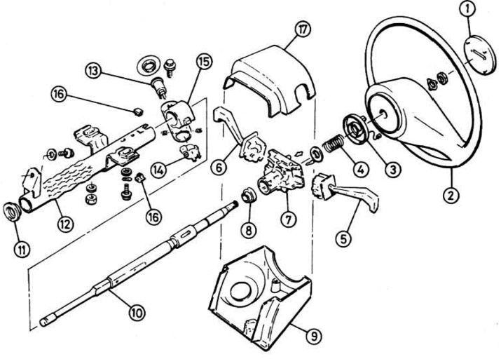
Fig. 10.22. Steering column and its parts:
1 - Horn button, 2 - Steering wheel, 3 - Cam assembly, 4 - Spring, 5 - Light switch, 6 - Windscreen wiper/washer switch, 7 - Switch housing, 8 - Bearing, 9 - Lower column housing, 10 - Steering wheel shaft, 11 - Plastic centering disc, 12 - Column tube, 13 - Lock cylinder, 14 - Lock cylinder, 15 - Lock housing, 16 - Safety plugs in switch housing, 17 - Upper column housing
Disassembly
If the steering column is not removed from the vehicle, perform the operations described above in the section "Steering column lock" in the first four points.
Remove the safety plugs in the ignition switch housing, then turn the housing counterclockwise and remove it.
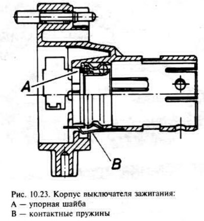
The bearing can be removed from the ignition switch housing by spreading the two bearing retaining latches apart and by pressing or knocking the bearing out with a tube of the appropriate diameter along the outer bearing ring. When pressing in a new bearing, make sure that the thrust washer and contact springs are installed correctly (fig. 10.23.).
Source is on this resource OpelBook.ru
The ignition switch is secured to the lock housing with two countersunk screws. Remove the screws to remove the switch. It is recommended not to remove the switch and the lock cylinder at the same time, otherwise their relative position will be disturbed.
If the steering column is installed, remove the upper pinch bolt from the steering wheel shaft flexible coupling in the driver's footwell.
Remove the steering wheel shaft from the steering column tube.
Assembly
Install the plastic centering disc that comes with the new column and steering wheel shaft into the base of the column tube.
Insert the shaft into the column tube, and if the column is in place, engage the lower end of the shaft with the elastic coupling and install the upper clamp bolt, but do not tighten it.
Where required, install the ignition switch and tighten the countersunk screws.
Install the ignition switch housing and fit new fuse plugs.
If the column is in place, pull up on the steering wheel shaft until the shaft contacts the bearing stop, then tighten the upper clamp bolt of the flexible coupling. Check that the road wheels are straight and that the flexible coupling is positioned so that the upper clamp bolt is horizontal on the top side of the steering wheel shaft.
Where required, further assembly is carried out in the reverse order of removal. Install the steering wheel as described above in the section "Steering wheel".
After completing the work, first perform low-speed maneuvers with the vehicle, then perform a test drive along a route with several turns and make sure that the steering mechanism operates smoothly.
Visitor comments