
OpelBook.ru
Cars AvtoVAZ Cars Mitsubishi Cars BMW Cars Mercedes Cars Nissan Cars Toyota Cars Chevrolet
English Русский
Български
Беларускі
Український
Српски
Hrvatski
Română
Polski
Slovenský
Magyar
 |  Sitemap  |  Contacts  |    


Main Astra Corsa Insignia Kadett Omega Vectra Zafira Others Articles
Astra F (1991-1998, petrol) Astra G (1998-2004, petrol) Astra G (1998-2004) Astra H (2004-2009) Astra J (2009-2015, petrol)
  • Main
  • Astra
  • Astra F
  • Electrical equipment
  • Equipment and devices
  • Auxiliary Warning System Components — Removal and Installation

Auxiliary Warning System Components — Removal and Installation (Opel Astra F)

            0

Contents: Control module ⬇ Multifunctional display ⬇ Coolant level sensor ⬇ Flushing fluid level sensor ⬇ Brake fluid level sensor ⬇ Engine oil level sensor ⬇ Brake pad wear sensors ⬇ Outside air temperature sensor ⬇
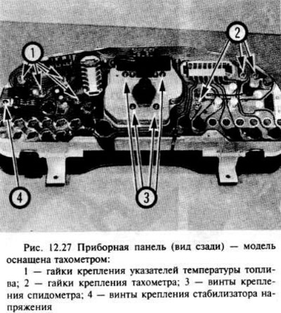
Auxiliary Warning System Components — Removal and Installation


Control module


The control module is made as a single unit with the multifunctional display (there is a section about it above).

Multifunctional display


See section above.

Coolant level sensor


Warning: Do not attempt to remove the coolant expansion tank cap/level sensor while the engine is hot, as this may cause a burn! The pressure in the cooling system must be relieved first. Cover the cap with a thick cloth to avoid burning and slowly unscrew it until the hissing stops.


The coolant level sensor is made as a single unit with the expansion tank cap.

Before removing the cover/sensor assembly, disconnect the negative battery terminal and the plug contact on the top of the sensor.

Installation is carried out in the reverse order of removal.

Flushing fluid level sensor


If possible, drain the fluid from the reservoir by turning on the washers to reduce fluid leakage while removing the level sensor.


Disconnect the negative battery terminal.

Disconnect the plug contact from the sensor, which is located on the side of the flushing fluid tank.

Loosen the sensor mounting screw.

Installation is carried out in the reverse order of removal.

Brake fluid level sensor


Note: Brake fluid is toxic; remove any liquid that comes into contact with your skin immediately by rinsing thoroughly; seek immediate medical attention if the fluid is swallowed or gets into your eyes. Some types of brake fluid are flammable and can ignite even on contact with hot surfaces. The fluid is also very strong on some plastics and will wash off paint, so if there is a spill, wash it off with plenty of clean water.


The low brake fluid warning sensor is installed on the brake fluid reservoir cap.

Before removing the cover/level sensor assembly, disconnect the negative battery terminal and the plug contact on the top of the sensor.

Installation is carried out in the reverse order of removal.

Engine oil level sensor


The engine fluid level sensor is located at the front end of the oil pan.
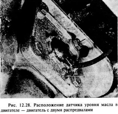
The engine fluid level sensor is located at the front end of the oil pan.


On DOHC models, remove the hatch to access the lower engine splash guard.


Disconnect the negative battery terminal, then the sensor plug.

Place a suitable container under the oil pan to collect any oil that may leak out while you are removing the sensor.

Loosen the screws and remove the sensor from the oil pan.

Remove the sealing ring.

Installation is carried out in the reverse order of removal, however, before installing the sensor, check the condition of the sealing ring and replace it if necessary.

Brake pad wear sensors


The sensors are in the form of wires located on the brake pads of the front brake mechanisms.

Removal and installation: as indicated in chapter 9.

Outside air temperature sensor


The sensor is secured with a clip to the lower edge of the front spoiler.
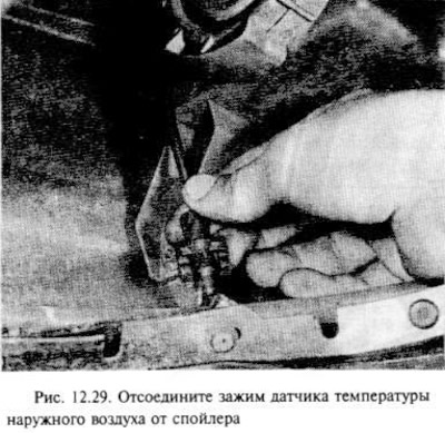
The sensor is secured with a clip to the lower edge of the front spoiler.


Disconnect the negative battery terminal.

For better access, apply the handbrake, then use a jack to raise the front of the car and secure it with stands under the axle.

Disconnect the sensor clamp from the spoiler, then disconnect the wire, noting its location.

Installation is carried out in the reverse order of removal, making sure that the wire connection is made in the same way as before removal.


This article is available at russian, bulgarian, belarusian, ukrainian, serbian, croatian, romanian, polish, slovak, hungarian
Checking the article: Trifonova Emilia

Share information:

Previous articles
Opel Astra F: Equipment and devices
Next articles

Auxiliary warning system
Clock and multifunction display — removal and installation
Instrument cluster components — removal and installation
Instrument panel — removal and installation
Switches — removal and installation
Fuses and relays — checking and removing
Trip computer — general information
Sound signal — removal and installation
Speedometer Flexible Shaft — Removal and Installation
Windscreen wiper arms — removal and installation
Rear Door Wiper Motor and Arm — Removal and Installation
Windshield/Rear Door Washer System Components — Removal and Installation


See similar ones from other Opel car manuals:
▶ Checking the proper functioning and condition of the… Opel Corsa B (1993-2000)
▶ Precautions when working with Supplemental Restraint System… Opel Insignia A (2008-2017)
▶ Distinctive components of the Motronic ML4.1 system from… Opel Kadett E (1984-1995)
▶ Electrical components of the transmission control system —… Opel Omega B2 (1999-2003)
▶ Injection system components Opel Vectra B (1995-2002, petrol)
Link to this page in different formats

Visitor comments


No comments yet


How much will 44 + 24 =


Astra J (2009-2015, petrol) 
  • General information
  • Vehicle device
  • User manual
  • Faults en route
  • Maintenance
  • Power unit
  • Engine repair
  • Cooling and lubrication system
  • Engine power system
  • Exhaust system
  • Transmission
  • Clutch
  • Car gearbox
  • Drive shafts
  • Chassis
  • Front suspension
  • Rear suspension
  • Steering
  • Brake system
  • Wheels and tires
  • Body
  • Exterior
  • Interior
  • Doors and windows
  • Body Care
  • Heating and air conditioning
  • Security systems
  • Electrical equipment
  • Equipment and devices
  • Lighting and signaling
  • Power devices
  • Electrical circuits
Astra H (2004-2009) 
  • General information
  • Introduction to the guide
  • Troubleshooting
  • User manual
  • Maintenance
  • Power unit
  • Engine repair
  • Cooling and heating
  • Power and exhaust system
  • Ignition system
  • Launch and charge system
  • Transmission
  • Mechanical gearbox
  • Automatic gearbox
  • Drive shafts
  • Chassis
  • Brake system
  • Car suspension
  • Steering
  • Body
  • Interior
  • Exterior
  • Electrical equipment
  • Equipment and devices
  • Electrical circuits
Astra G (1998-2004) 
  • General information
  • Introduction to manual
  • User manual
  • Maintenance
  • Power unit
  • SOHC gasoline engines
  • DOHC gasoline engines
  • Diesel engines 1.7 and 2.0
  • Engine repair
  • Cooling system
  • Supply system
  • Injection system (gasoline)
  • Injection system (diesel)
  • Exhaust system
  • Charge and launch system
  • Ignition system (gasoline)
  • Preheat system (diesel)
  • Transmission
  • Manual gearbox
  • Automatic gearbox
  • Clutch
  • Drive shafts
  • Chassis
  • Brake system
  • Wheel suspension
  • Steering
  • Body
  • Exterior
  • Interior
  • Doors and windows
  • Ventilation and heating
  • Electrical equipment
  • Equipment and devices
  • Electrical circuits
Astra G (1998-2004, petrol) 
  • General information
  • User manual
  • Car care
  • Maintenance
  • Power unit
  • Single shaft engines
  • Twin shaft engines
  • Engine repair
  • Cooling and heating
  • Fuel and exhaust systems
  • Starting and charging system
  • Ignition system
  • Transmission
  • Clutch
  • Mechanical gearbox
  • Automatic gearbox
  • Drive shafts
  • Chassis
  • Brake system
  • Car suspension
  • Steering
  • Body
  • Interior
  • Exterior
  • Electrical equipment
  • Equipment and devices
  • Wiring diagrams Opel Astra
  • Wiring diagrams Opel Zafira
Astra F (1991-1998, petrol) 
  • General information
  • Maintenance
  • Power unit
  • Engine in car
  • Engine removed
  • Cooling system
  • Heating and ventilation
  • Fuel supply (carburetor)
  • Fuel supply (injector)
  • Emission control
  • Ignition system
  • Transmission
  • Clutch
  • Mechanical gearbox
  • Automatic gearbox
  • Drive shafts
  • Chassis
  • Brake system
  • Car suspension
  • Steering
  • Body
  • Exterior
  • Interior
  • Electrical equipment
  • Equipment and devices
  • Electrical circuits
OpelBook.ru © 2017–2026 · Mobile version · · Sitemap: EN BG BY UA RS HR RO PL SK HU · Feedback · Site search
Astra F, petrol · Astra G, petrol · Astra G · Astra H · Astra J, petrol · Corsa B · Corsa C, petrol · Corsa C · Insignia A · Kadett D · Kadett E · Omega A · Omega B · Omega B2 · Vectra A, petrol · Vectra A · Vectra B, petrol · Vectra B · Vectra C · Zafira A, petrol · Frontera A, petrol · Frontera B · Ascona C · Vivaro A ·
We want your visit to be comfortable 🤝! We use cookies 🍪 to make that happen.