
Pilot lamps and paws of illumination of the panel
Removing
2. Turn the appropriate bulb socket clockwise and remove it from the printed circuit board at the back of the dashboard (see illustration).
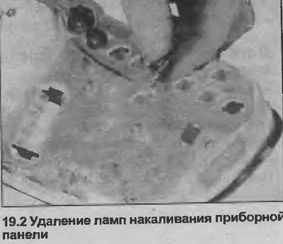
3. The bulbs are built into the bulb holders and must be replaced as a unit.
Installation
4. Installation is carried out in the reverse order.
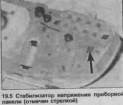
Voltage regulator
Removing
5. Loosen the fixing screw on the back of the instrument panel, then disconnect the voltage regulator from the contacts of the printed circuit (see illustration).
Installation
6. Installation is carried out in the reverse order.
Fuel and temperature gauges - low end models
Removing
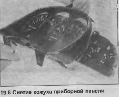
7. Disconnect the trip meter installation pin from the front of the panel.
8. Release the two mounting brackets on top of the panel and remove the group cover (see illustration).
9. Turn off two fixing nuts and take the corresponding sensor from the dashboard.
Installation
10. Installation is carried out in the reverse order.
Fuel and temperature gauges - high end models
11. The procedure is the same as in steps 7-10, except that the sensor assembly is secured with four nuts.
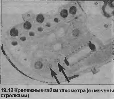
Tachometer
12. The procedure is the same as described in paragraphs 7-10, except that the tachometer is attached with three nuts (see illustration).
Speedometer
Removing
13. Proceed as described in points 7 and 8.
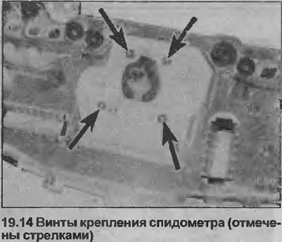
14. Remove the four screws securing the back of the panel (see illustration).
Installation
15. Installation is carried out in the reverse order.
Printed circuit
Removing
16. Remove all lamps, devices and the voltage regulator as it is described previously in this Chapter.
17. Carefully remove the printed circuit from the dashboard.
Installation
18. Installation is carried out in the reverse order, but make sure that the printed circuit is placed correctly on the back of the dashboard.
Visitor comments