


Contents: Early models ⬇ Latest models ⬇
Early models
1. Set the gear shift lever to neutral, detach its rubber boot from the floor and lift it up the lever.
2. If there is a center console, depending on its type, it may be necessary to remove it in order to gain access to the base of the lever (see chapter 11).
3. Remove the retaining ring from the groove on the lever body.
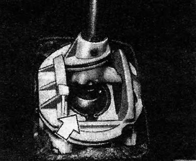
Figure 6.3. Gear shift lever retaining ring (shown by arrow) on early models
4. Press the lever to the left and pull it out.
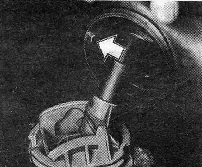
Figure 6.4. Gear shift lever mounting tab (shown by arrow) on early models
5. If necessary, the lever housing together with the insulator can be removed from below. The lever housing can only be replaced as an assembly.
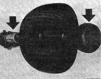
Figure 6.5. Position of the gearshift lever handle relative to the reverse clutch on early models (shown by arrows)
6. If it is necessary to replace the rubber cover of the lever, the handle should be removed from the lever, after heating it in very hot water.
7. Install the gear shift lever in the reverse order. Please note the following points:
- a. Apply a small amount of grease to the ball joint of the control arm.
- b. Please note that the tongue on the inside of the rubber boot should be facing the front of the vehicle.
- c. When installing the gear shift lever handle, it must be aligned with the stop on the reverse clutch.
Latest models
8. Follow the instructions in paragraphs 1 and 2.
9. Remove the 4 bolts securing the base of the lever to the floor and remove the lever (see photo).
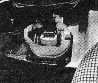
Photo 3.9. Fastening the gearshift lever to the passenger compartment floor on the latest models.
10. To remove the gearshift lever housing, pry up and remove the C-clamp, pull out the pin and remove the housing from the lower end of the lever (see photos).
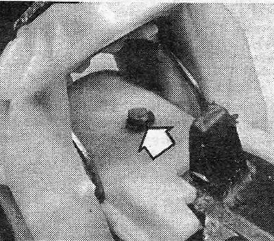
Photo 3.10A. Remove the C-clamp (shown by arrow) from the groove on the pin...
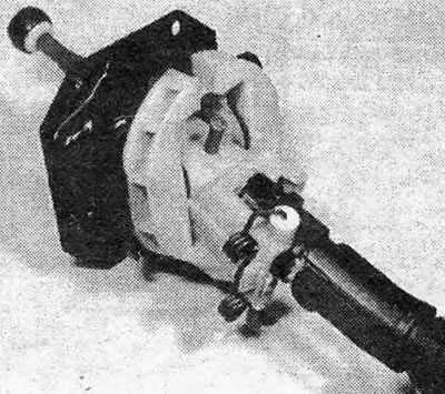
Photo 3.10B....pull out the pin...
Text copied from this portal www.OpelBook.ru
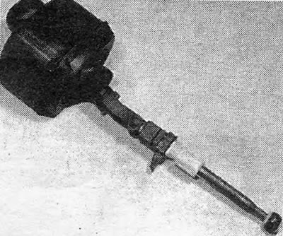
Photo 3.10C....and disconnect the lever from the body (latest models).
11. To remove the rubber boot of the lever ball, pry it up and pull it out of the groove on the ball (see photo).
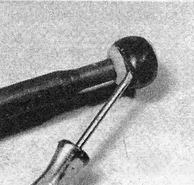
Photo 3.11. Removing the rubber insulator from the gear shift lever ball (latest models).
12. The handle and rubber boot of the lever are removed in the same way as on earlier models (see paragraph 6).
13. If necessary, you can remove the gear shift lever linkage, but first pay attention to the position of all parts in order to facilitate their subsequent installation.
14. Install the gear shift lever in the reverse order. Please note the following points:
- a. Lubricate the ball joint of the lever with grease.
- 6. Before installing the lever, check that all parts of the gear shift mechanism are correctly oriented relative to each other and that the lever handle is correctly installed.
- c. After installing the lever, check that when the lever is in the neutral position, the marks on the side of the lever housing and on the lever itself are aligned (see photo).
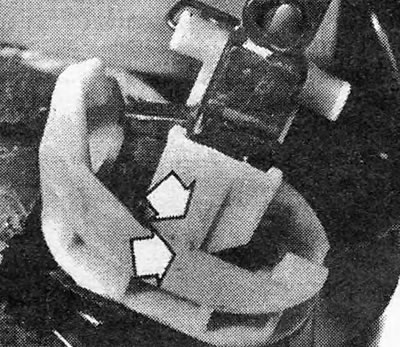
Photo 3.14. Neutral position alignment marks on the gearshift housing and lever (shown by arrows) (latest models).
Visitor comments