
Note: before pressing the shaft out of gears, synchronizers, etc., the parts being released should be securely supported. Likewise, if a puller is used, you should check that its jaws are on the body of the part being removed and in no case on the teeth, for example, a gear. In extreme cases, if the part is not performing well, you can carefully heat it, but not more than 100°C.
1. Remove the retaining ring from the bearing at the end of the shaft (see photo).
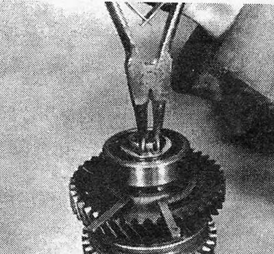
Photo 12.1. Removing the driven shaft bearing retaining ring.
2. Support the 1st gear gear and drive the shaft out of the bearing and out of the gear. Note the spacer between the bearing and gears (see photos). On some recent models, a radial needle bearing is installed instead of a spacer. In this case, it is necessary to remove both this bearing and the gear bearing.
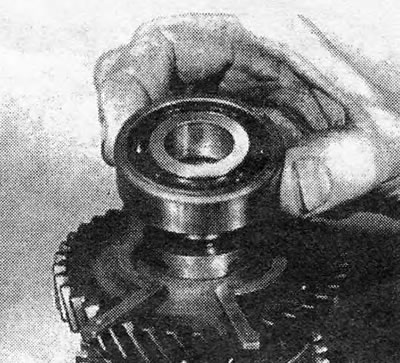
Photo 12.2A. Removing the driven shaft bearing.
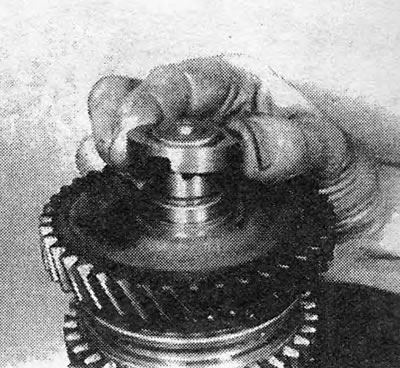
Photo 12.2V. Removing the spacer washer from the 1st gear.
Note: some models may have a needle bearing instead of a spacer.
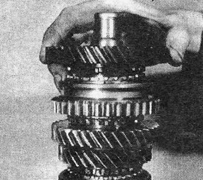
Photo 12.2C. Removing the 1st gear gear.
3. Support the 2nd gear and remove the retaining ring securing the 1/2 gear synchronizer (see photo).
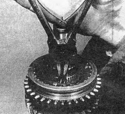
Photo 12.3. Removing the retaining ring from the 1/2 gear synchronizer.
4. Remove the cone ring from the shaft (see photo).
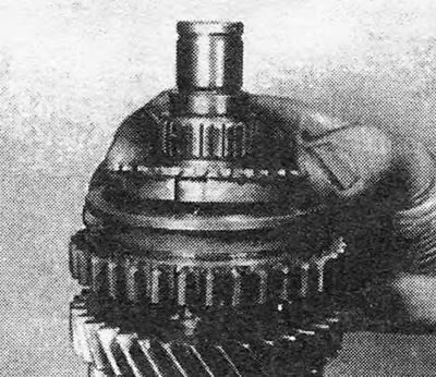
Photo 12.4. Removing the 1/2 gear synchronizer cone ring.
5. Attach a puller or press plate under the 2nd gear.
6. Press out or remove the 2nd gear and the 1st/2nd gear synchronizer from the shaft.
7. Disconnect the 2nd gear from the synchronizer and remove the 2nd gear cone ring.
8. Go to the other end of the shaft and remove the retaining ring securing the main gear drive gear to the shaft (see photo).
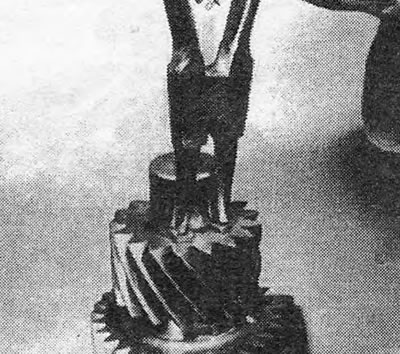
Photo 12.8. Removing the retaining ring from the main gear drive gear.
9. Remove the drive gear (see photo).
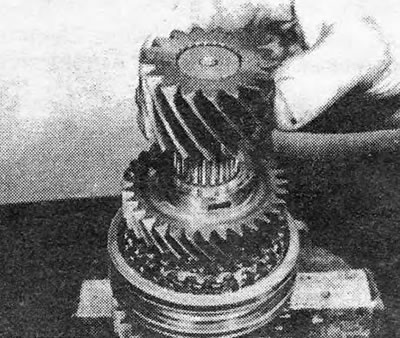
Photo 12.9. Removing the main gear drive gear.
10. Remove the spacer washer (see photo).
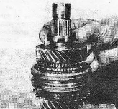
Photo 12.10. Removing the spacer washer from the 4th gear.
11. Remove 4th gear (see photo).
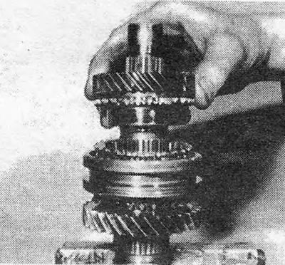
Photo 12.11. Removing the 4th gear gear.
12. Remove the cone ring (see photo).
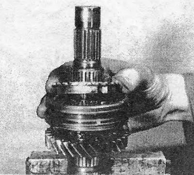
Photo 12.12. Removing the cone ring from the 4th gear gear.
13. Remove the retaining ring securing the 3/4 gear synchronizer to the shaft (see photo).
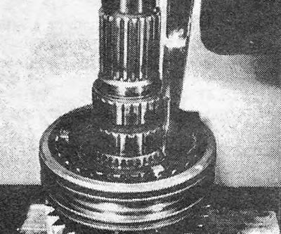
Photo 12.13. Removing the retaining ring from the 3/4 gear synchronizer.
14. Remove 3/4 gear synchronizer (see photo).
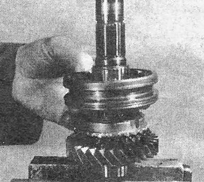
Photo 12.14. Removing the 3/4 gear synchronizer.
15. Remove the next cone ring (see photo).
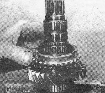
Photo 12.15. Removing the cone ring from the 3rd gear gear.
16. Remove 3rd gear (see photo).
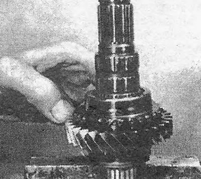
Photo 12.16. Removing the 3rd gear gear.
17. Inspect all gears for damaged or worn teeth, and the shaft for worn splines.
18. Replace all retaining rings. Compare new parts with old ones to ensure they are identical. This is especially important when replacing the following parts that were modified in April 1986:
- A. The 1st gear gear cones have been increased in diameter to 58 mm instead of the previous 51 mm. The 1st gear fork has been similarly modified and is not interchangeable with the fork on earlier models.
- b. Ball bearings with mounting grooves are now closed (previously open type bearings were used).
- V. On the F10.4 gearbox, 2 modifications were made to the 1st gear gear. The gear now rests on a needle bearing with a split cage, and in addition, instead of a spacer washer, a radial needle bearing is installed (see boxes in Fig. 6.19).
19. If gear shifting was accompanied by noise or the synchronizers did not work well, the synchronizer assembly should be replaced or rebuilt (see next section).
20. Clean and oil all parts, and then assemble them in the sequence shown below. If necessary, parts must be pressed onto the shaft using a tube of suitable size, which would rest on the body of the part, and not on its teeth.
21. Install the 3rd gear on the end of the shaft where the main gear drive gear is located.
22. Install the cone ring on the 3rd gear gear cone.
23. Install 3/4 gear synchronizer (pressure must be applied to its hub) (see photo). It is recommended to preheat the synchronizer to 100°C.
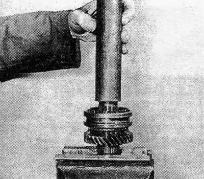
Photo 12.23. Using a tube, press the 3/4 gear synchronizer into place.
24. Secure the synchronizer with a new locking ring.
25. Install the cone ring and 4th gear.
26. Install the spacer washer and the main drive gear. It is recommended to preheat both of these parts to 100°C.
27. Secure the main gear drive gear with a new locking ring.
28. Go to the other end of the shaft and install the 2nd gear (see photo).
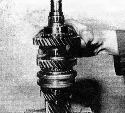
Photo 12.28. Installing the 2nd gear.
29. Install the cone ring on the 2nd gear cone.
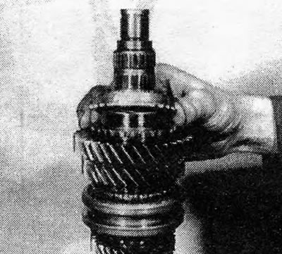
Photo 12.29. Installing the 2nd gear cone ring.
30. Heat the 1/2 gear synchronizer to 100°C and press it onto the shaft with the teeth of the reverse gear towards the 2 gear gear (see photo).
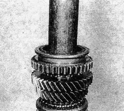
Photo 12.30. Installing 1/2 gear synchronizer - pay attention to the position of the reverse gear teeth.
31. Secure the synchronizer with a new locking ring.
32. Install the cone ring of the 1st gear gear and the 1st gear itself.
33. Heat the spacer washer to 100°C and press it onto the shaft with the grooves towards the 1st gear gear (see photo).
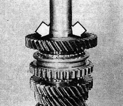
Photo 12.33. Grooves on the spacer (shown by arrows) should be on the 1st gear side.
34. Place a new retaining ring on the shaft so that it is ready for installation in its groove on the box housing.
35. Install the bearing and secure it with a new retaining ring.
Visitor comments