
2. Install the semi-axial gears and satellites, spring discs and the satellite axis into the differential box.
3. Install new retaining rings.
4. If you removed the speedometer drive gear, heat the new gear in hot water to 80°C and use a tube to drive it onto the differential box so that it snaps into place. Check that the lugs on the gear housing are aligned with the cutouts in the differential box.
5. Heat the main drive driven gear to 80°C and install it on the differential box. Insert new bolts and tighten them to the required torque.
6. Install new tapered roller bearings on the differential box (if they were removed during disassembly).
7. If this has not already been done, install the outer bearing tracks into the box housing.
8. Install new drive shaft seals into the gearbox housing (if it hasn't been done yet) and fill the space between their jaws with lubricant.
9. Lower the differential into the gearbox housing.
10. Install the O-ring and oil seal on the bearing adjusting ring. Apply lubricant to the seal lips and the threads of the adjusting ring (see photos).
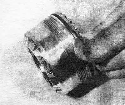
Photo 14.10A. Bearing adjusting ring seal.
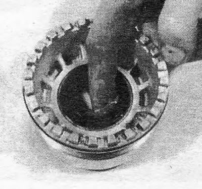
Photo 14.10B. Fill the space between the seal lips with lubricant.
11. Screw the adjusting ring into the gearbox housing and at this stage tighten it by hand (see photo).

Photo 11/14. Installing the bearing adjusting ring.
12. Adjust the bearing using one of the following methods: (depending on whether the bearings were replaced or not).
13. Old bearing: screw in the adjusting ring so that the alignment marks made when disassembling the box are opposite each other. If there is axial play, the ring can be screwed in further to achieve a torque of 5.3-8.9 lb-ft (For the procedure see below, as for the case of a new bearing).
14. New Bearing: Bearing preload should be adjusted using the adjusting ring so that 13.3-15.9 lb-ft of torque is required to slowly rotate the final drive gear and bearing. If you do not have a special device for determining torque, you should insert a tapered wooden stick (soft wood) into the splines of the semi-axial gear, wrap the stick with twine and attach the other end of the twine to the spring scales. If the radius of the stick where the string extends from it is about 1.0 inches, you will get a fairly accurate torque value. Adjust the position of the adjusting ring until the desired torque is obtained.
15. Install the adjusting ring locking plate, being careful not to dislodge its position. Especially for this purpose, the hole for the locking plate bolt is made longer.
16. Bolt the pressed steel cover with a new gasket to the transmission housing.
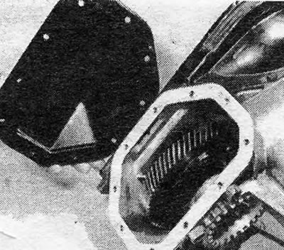
Photo 14.16. Installing a pressed steel cover with a new gasket.
17. Install the reverse intermediate gear axis into the end cover of the box, checking that the locking ball is in place.
18. Secure the 1/2 gear fork with a pin to its rod, but leave the pin protruding approximately 2.0 mm.
19. Assemble and engage the gear blocks of the driven shaft, drive shaft and reverse gear so that the 1/2 gear fork, installed on its rod, stands in the groove on the 1/2 gear synchronizer.
20. Install the assembled assembly into the end cover. The work will be much easier if you have an assistant. Install the stem locking plunger (see photos).
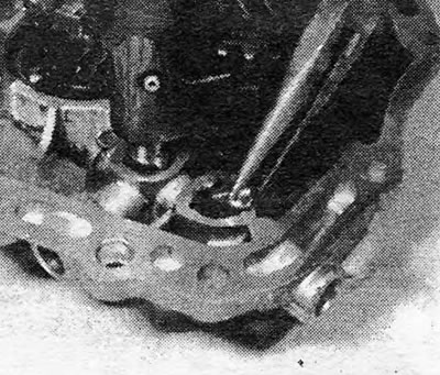
Photo 14.20A. Installing the short locking plunger.
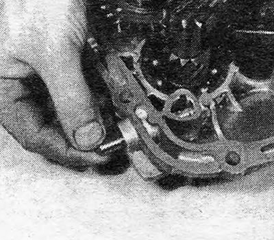
Photo 14.20B. Installing the long locking plunger.
21. Install retaining rings holding the driven and drive shafts in the gearbox housing. Check that the rings fit into the grooves intended for them. Install the thrust washer onto the reverse idler gear. Install a magnet to collect metal dust (see photos).
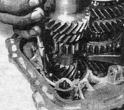
Photo 14.21 A. Installing the drive shaft retaining ring into the groove on the gearbox housing.
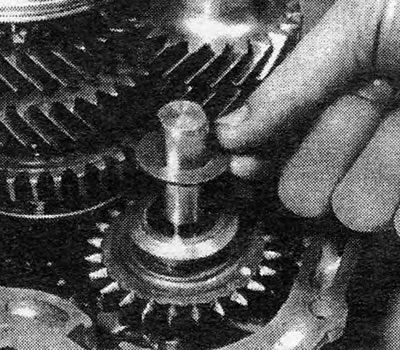
Photo 14.21B. Reverse idler gear thrust washer.
22. Check that the 1/2 gear synchronizer clutch is in the neutral position, and install the forks and rods of 3/4 gears and reverse gears (see photos).
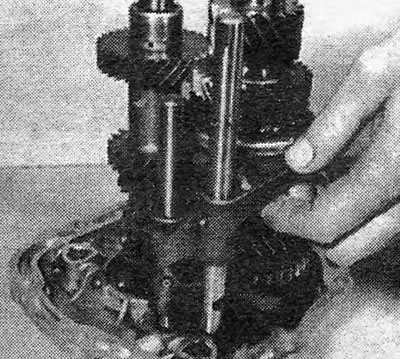
Photo 14.22A. Installation of the 3/4 gear fork and rod.
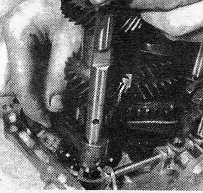
Photo 14.22V. Installing the fork and reverse rod.
23. Fix the forks with pins on their rods (see photos).
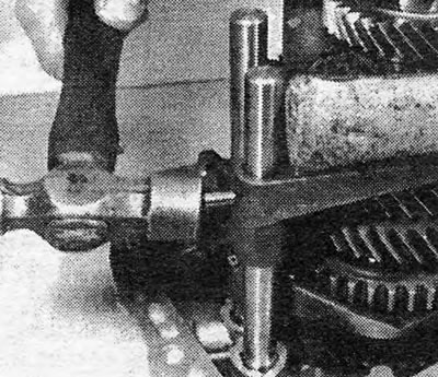
Photo 14.23A. Installing the pin securing the 1/2 gear fork to its rod.
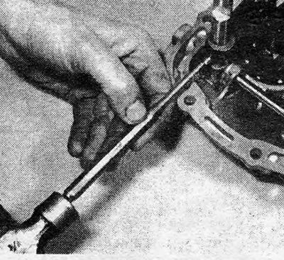
Photo 14.23B. Installing the pin securing the reverse fork to its rod.
24. Install the plungers and retainer springs. If the sealing plugs of the clamps do not hold well enough, they should be replaced with larger plugs.
25. Using a screwdriver, move the clutch of the corresponding synchronizer so as to engage 2nd gear.
26. Install a new gasket on the gearbox housing, securing it in place with grease, and reinstall the end cover along with the gear blocks. Insert the mounting bolts and nuts and tighten them to the required torque (see photo).
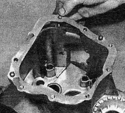
Photo 14.26. Installing the transmission housing gasket.
27. Install the speedometer driven gear and its locking plate. Secure the locking plate with bolts.
28. Screw in the reverse light switch and tighten it to the desired torque.
29. Place the transmission in neutral and install a new shift cover gasket, securing it in place with grease (see photo).
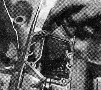
Photo 14.29. Installing the shift cover gasket.
30. Reinstall the gear shift cover and secure it with bolts. Tighten the bolts to the required torque.
31. Install the box on the car, connect it to the engine and fill the box with oil.
Visitor comments