
Note: The operations listed in paragraphs 6 and 7 must be performed while removing the box, and are listed here only to provide a complete picture of box disassembly.
1. Remove the box from the machine and clean the outside of it from dirt with kerosene or water-soluble solvent and a stiff brush.
2. Remove the bolts securing the main gear housing cover and allow the oil to drain.
3. Remove the bolts and remove the flywheel housing cover.
4. Remove the bolts, remove the gear shift mechanism cover and tear off the gasket from the flange.
5. Unscrew the bolts and remove the end cover of the box with its gasket.
b. Remove the exposed snap ring from the end of the drive shaft. This ring sits quite deep in its groove and requires special pliers to remove it.
7. Unscrew and remove the screw with a hole in the head for a 12-point socket (You can use a suitable hex wrench for this).
8. Remove the bolts and disconnect the main gearbox housing from the intermediate plate.
9. Using a hex wrench, remove the screws securing the 5th gear fork. The work will be easier if you first manually move the 5th gear synchronizer to the gear position.
10. Remove the retaining ring from the end of the driven shaft and, using a two-bearing puller, remove the gear and 5th gear synchronizer from the shaft. The puller jaws must be installed under the 5th gear.
11. Remove the retaining ring from the end of the drive shaft and remove the 5th gear from the shaft (big). To remove the gear, you can use two mounting tools, pressing the gear with them like levers (see photos).
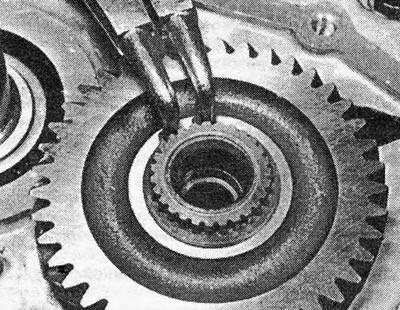
Photo 18.11A. Removing the retaining ring from the end of the drive shaft.
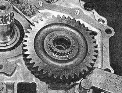
Photo 18.11B. Removing the 5th gear from the drive shaft using two mounts.
12. Using a hex key, remove the screws securing the locking pawl of the gear rod 5 to the intermediate plate.
13. Using a disconnector fork or a reverse hammer, remove the retainer plugs from the edge of the intermediate plate. Be prepared to catch the springs that will pop out once the plugs are removed. Pull out the clamp plungers (see photos).
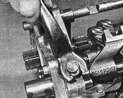
Photo 18.13A. Pry up and remove the locking plug.

Photo 18.13B. Homemade tool for removing the longer 3/4 gear retainer plug.
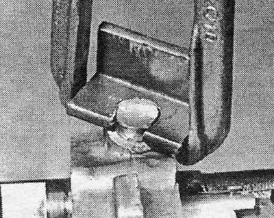
Photo 18.13С. A reverse hammer attached to a tool for removing the retainer plug.
14. Plugs damaged during removal must be replaced.
15. Move the gear rod 5 to the engaged gear position.
16. Move the 2nd gear fork to engage 2nd gear.
17. Using a hex wrench, remove the screws securing the locking plunger jumper. Remove the jumper.
18. Return the gears to the neutral position.
19. Drive out the cylindrical pin securing the 3/4 gear fork. Remove the stem and fork. Remove the reverse gear rod and fork in the same way.
20. Pull the locking rod out of the intermediate plate.
21. Pull the 5th gear rod driver out of the intermediate plate.
22. Drive out the cylindrical pin and remove the fork and 1/2 gear rod.
23. Press together the ends of the large snap ring securing the driven shaft bearing to the intermediate plate. Make a clamp from a thin rod and fix the locking ring in a compressed state.
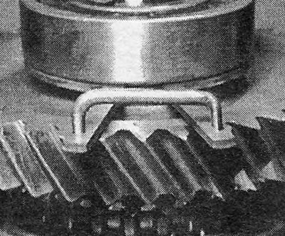
Photo 18.23. A clamp to hold the retaining ring in a compressed position.
24. Separate the ends of the retaining ring holding the drive shaft bearing in the intermediate plate.
25. Together with an assistant, pull out the gear blocks along with the reverse intermediate gear. It is possible that in order for the shafts with bearings to come out of the intermediate plate, you will have to knock on them with a hammer with a plastic striker. Pay attention to the washer on the reverse idler gear.
Drive shaft and gear block
26. Inspect the gear teeth for wear. If tooth wear is obvious, the gear unit must be replaced (see photo).
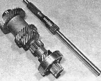
Photo 18.26. Drive shaft and its gear block.
27. Bearings can be replaced using a suitable puller.
28. The shaft can be knocked out of the gear block using a hammer with a plastic striker.
Driven shaft
29. Place the grips of a two-support puller under the 1st gear gear and remove the gear along with the ball bearings from the driven shaft (see photo).
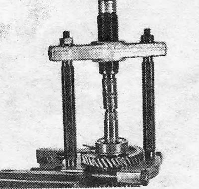
Photo 18.29. Removing the 1st gear gear with bearing from the driven shaft.
30. Remove the retaining ring. Remove the regular thrust washer and then the needle type thrust washer from the shaft.
31. Remove the cone ring of the 1st gear gear.
32. Remove the split needle roller bearing.
33. Remove the retaining ring.
34. Remove the regular thrust washer.
35. Place the puller grips under the 2nd gear and remove the 1/2 gear synchronizer with the reverse gear, the cone ring and the 2nd gear from the driven shaft. Note that the reverse gear teeth on the synchronizer clutch face the end of the shaft on which the final drive gear sits.
36. Remove the half-ring thrust washers and their retaining ring.
37. Remove the 3rd gear.
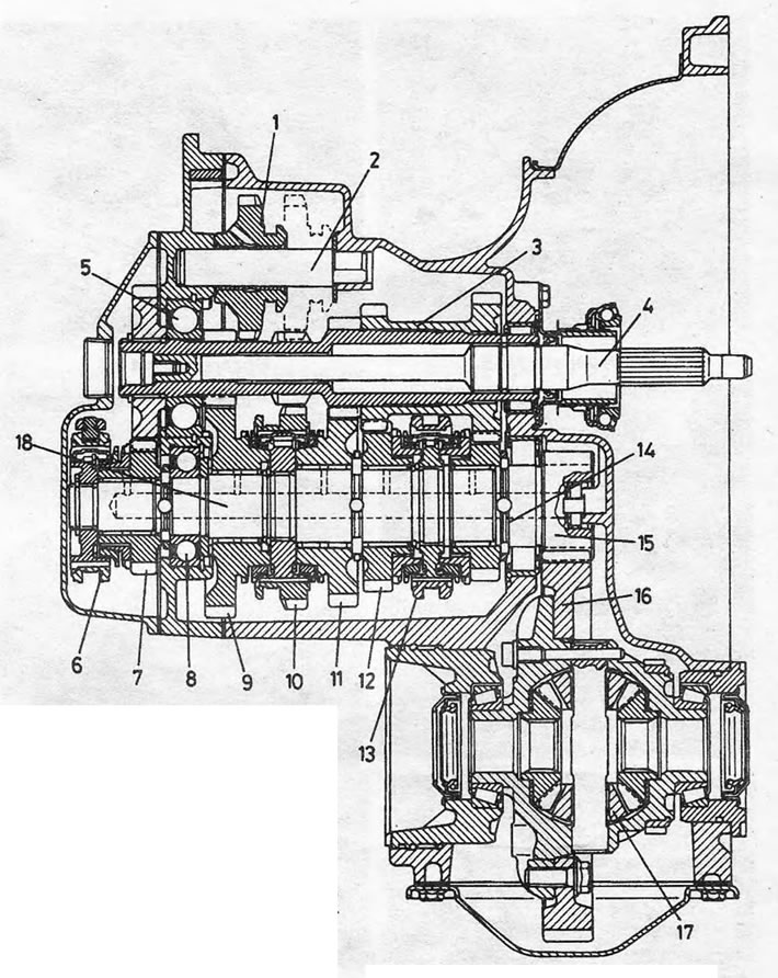
Pic. 6.37. Sectional view of the F16.5 manual gearbox: 1. Reverse intermediate gear; 2. Reverse idler gear axis; 3. Drive shaft gear block; 4. Drive shaft (can be removed from the gear block); 5. Ball bearing; 6. 5th gear synchronizer; 7. Gear 5th gear; 8. Ball bearing; 9. 1st gear gear; 10. 1/2 gear synchronizer with reverse gear; 11. Gear 2nd gear; 12. Gear 3rd gear; 13. 3/4 gear synchronizer; 14. Roller bearing; 15. Main gear drive gear; 16. Main gear driven gear; 17. Differential; 18. Driven shaft.
38. Remove the cone ring of the 3rd gear gear.
39. Remove the split needle roller bearing.
40. Remove the retaining ring securing the 3/4 gear synchronizer.
41. Remove the thrust washer.
42. Place the puller arms under the 4th gear and remove the 3/4 synchronizer, cone ring and 4th gear from the driven shaft.
43. Remove the split needle roller bearing.
44. Remove the half-ring thrust washers and their retaining ring.
45. Remove the roller bearing ring from the shaft. The main gear drive gear cannot be removed.
Synchronizers
46. See section 13.
Gearbox housing
47. See section 10 and photograph.
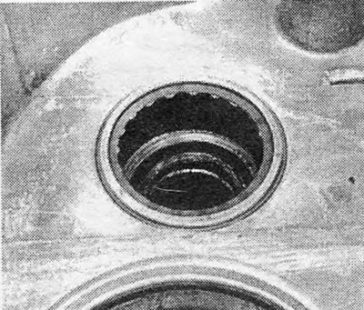
Photo 18.47. Bearing in the gearbox housing.
Gear shift mechanism cover
48. See section 9.
Differential and final drive.
49. Removal, installation and adjustment of the differential and main gear are carried out in the same way as described in sections 8 and 14.
Visitor comments