
Transmission
1. Remove the box from the machine and clean the outside of it from dirt using kerosene and a stiff brush or using a solvent.
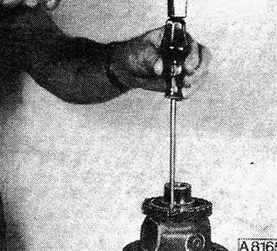
2. Unscrew the bolts and remove the gear shift mechanism cover from the gearbox housing (see photo).
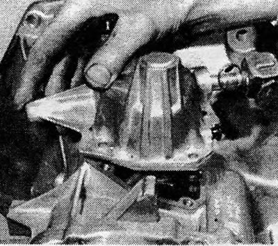
Photo 8.2. Removing the gearshift cover.
3. Remove the bolts securing the locking plate and remove the speedometer driven gear.
4. Unscrew and remove the reverse light switch and allow the oil to drain (see photo).
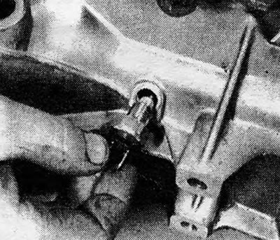
Photo 8.4. Removing the reverse light switch.
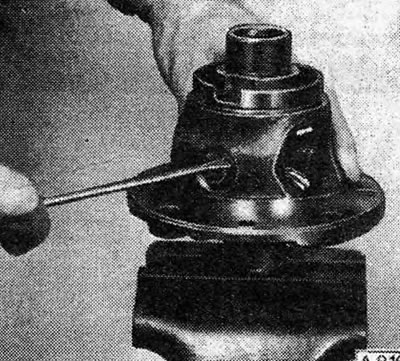
5. Using a screwdriver as a lever, engage 2nd gear by moving the fork closest to the end cap accordingly (see Fig.6.16).
6. Unscrew and remove the bolts and nuts of the end cover.
7. Remove the main crankcase from the end cover and gear blocks (see photo).
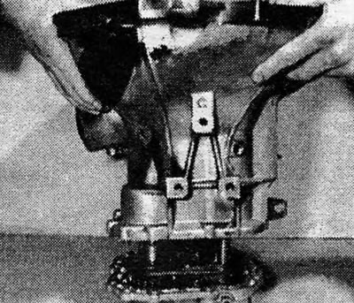
Photo 8.7. Removing the main gearbox housing.
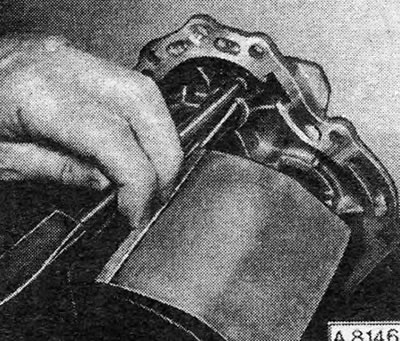
8. Pry and remove the gear lock plugs from the end cover. Pull out the springs and plungers of the clamps (see photos).
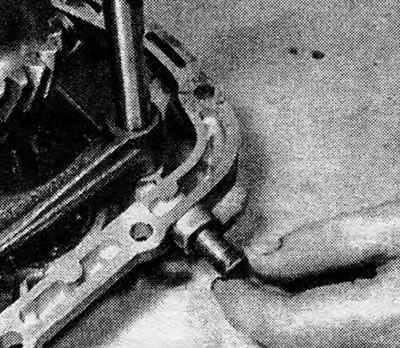
Photo 8.8A. Removing the retainer plug.
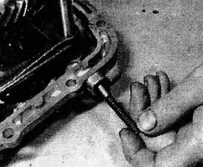
Photo 8.8B. Removing the spring and retainer plunger.
9. Drive out the cylindrical pins securing the gear forks to the rods.
10. Move the synchronizer clutch back to the neutral position and then remove the 3/4 and reverse gears and their rods from the end cover.
11. Remove the retaining rings securing the gear blocks of the driven and drive shafts of the box. Remove the magnet to collect metal particles (see photos).
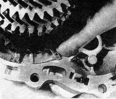
Photo 8.11A. Gearbox driven shaft retaining ring.
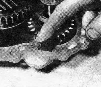
Photo 8.11B. Magnet for collecting metal particles.
12. Remove the gear blocks and the 1/2 gear fork together with its rod at the same time (see photo).
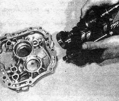
Photo 8.12. Removing the gear blocks from the end cover.
13. Pull the rod locking plungers out of the end cover.
14. Pull out the reverse idler gear axle from the end cover. To do this, clamp the axle in a vice with soft jaws and, using a brass bit, carefully remove the cover from it. Be careful not to lose the locking ball (see photo).
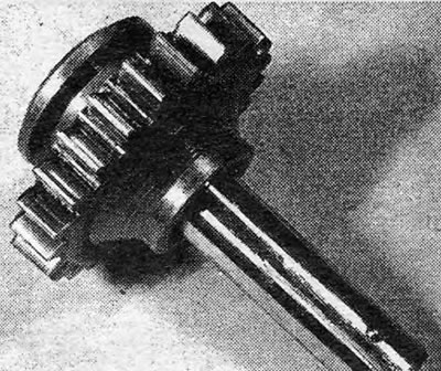
Photo 8.14. Reverse idler gear axis with locking ball.
Differential
15. Remove the bolts and remove the pressed steel cover from the box housing.
16. Mark the position of the bearing adjusting ring relative to the gearbox housing and remove the bolts of the ring locking plate (see photos).
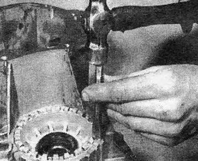
Photo 8.16A. Mark the position of the differential bearing adjusting ring.
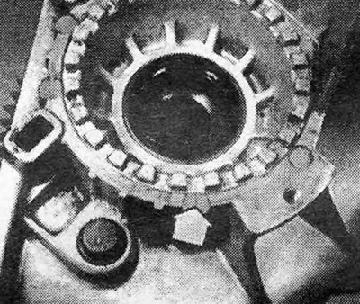
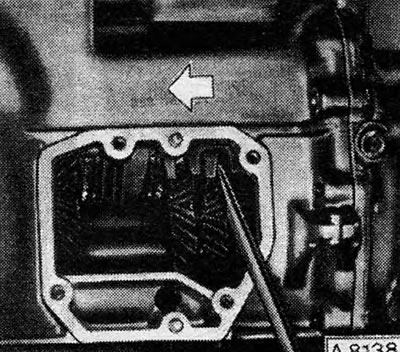
Photo 8.16B. Bearing adjusting ring alignment marks (shown by arrow).
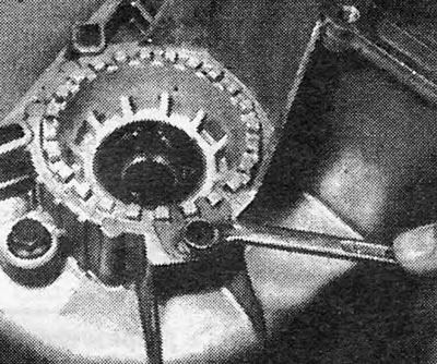
Photo 8.16С. Remove the bolts securing the adjusting ring locking plate.
Pic. 6.16. Engaging 2nd gear: Move the fork in the direction shown by the arrow.
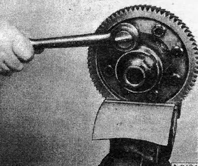
17. Unscrew the adjusting ring (You can use a long steel plate as a key) (see photo).
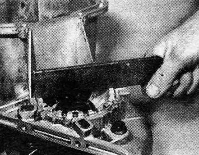
Photo 8.17. Unscrew the bearing adjusting ring.
Pic. 6.17. Remove the end cap from the reverse idler gear axle.
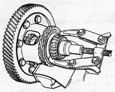
18. Pull out the differential with the driven gear of the main drive (see photo).
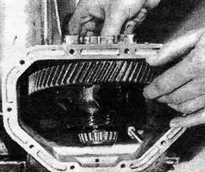
Photo 8.18. Removing the differential with the main drive driven gear.
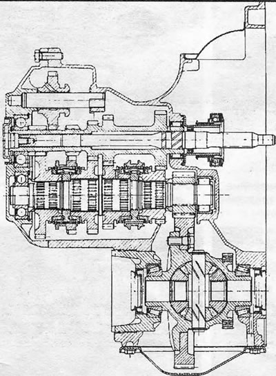
Pic. 6.18. Sectional view of manual transmission type F10.4
19. Depending on whether the box is being disassembled due to leaking oil seals or due to bearing wear, the following should be done.
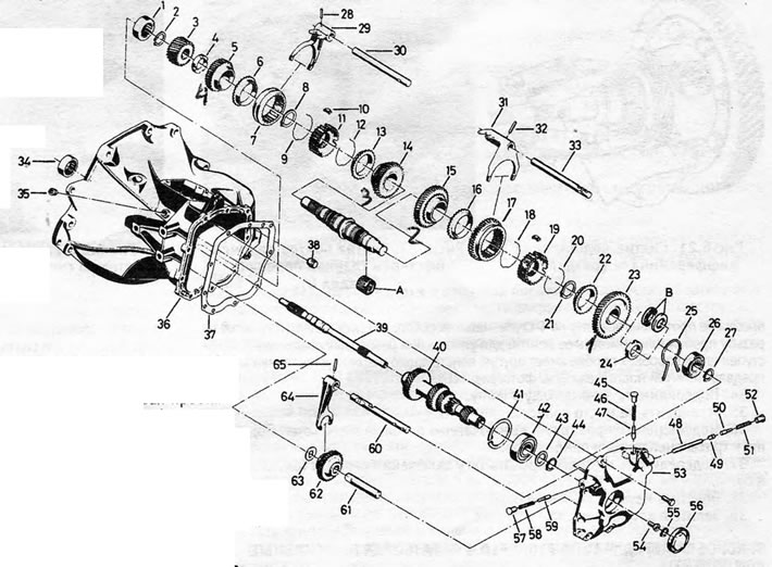
Pic. 6.19. Gearbox F10.4 disassembled: 1. Drive shaft roller bearing (is in the crankcase); 2. Retaining ring; 3. Main gear drive; 4. Spacer washer; 5. Gear 4th gear; 6. Cone ring; 7. Synchronizer clutch 3/4 gears; 8. Retaining ring; 9. Synchronizer spring; 10. Sliding key; 11. Synchronizer hub 37 3/4 gears; 12. Synchronizer spring; 13. Cone ring; 14. Gear 3rd gear; 15. Gear 2nd gear; 16. Cone ring; 17. 1/2 gear synchronizer clutch with reverse gear; 18. Synchronizer spring; 19. 1/2 gear synchronizer hub; 20. Synchronizer spring; 21. Retaining ring; 22. Cone ring; 23. 1st gear; 24. Spacer washer; 25. Drive shaft retaining ring; 26. Rear ring; 27. Retaining ring; 28. Straight pin; 29. 3/4 gear fork; 30. Rod; 31. 1/2 gear fork 35; 32. Straight pin; 33. Rod; 34. Needle bearing (in the box housing); 35. Cork; 36. Carter; 37. Gasket; 38. Cork; 39. Drive shaft; 40. Drive shaft gear block; 41. Retaining ring of the drive shaft gear block; 42. Bearing; 43. Thrust washer; 44. Retaining ring; 45. Retainer plug; 46. Retainer spring; 47. Retainer plunger; 48. Long locking plunger; 49. Short locking plunger; 50. Retainer plunger; 51. Retainer spring; 52. Retainer plug; 53. End cap; 54. Drive shaft screw; 55. Retaining ring; 56. Screw plug; 57. Retainer plug; 58. Retainer spring; 59. Retainer plunger; 60. Reverse rod; 61. Reverse intermediate gear axis; 62. Reverse intermediate gear; 63. Thrust washer; 64. Reverse fork; 65. Straight pin; A. Needle bearing on early models; B. Bearing installed on the latest models instead of a spacer washer (24).
20. Replace oil seals and bearings in the adjusting ring and box housing, removing old parts and installing new ones using a metal tube (see photos).
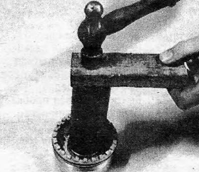
Photo 8.20A. Installing the bearing adjusting ring seal.
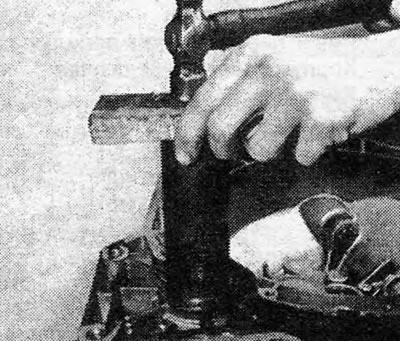
Photo 8.20B. Installing the differential seal.
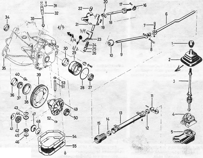
Pic. 6.20. Details of the differential and gear shift mechanism on the F10.4 type gearbox: 1. Gear shift knob; 2. Rubber cover; 3. Gear shift lever; 4. Gear shift lever housing; 5. Case; 6. Traction; 7. Connecting pin; 8. Connecting pin; 9. Traction; 10. Cap; 11. Intermediate gear shift lever; 12. Bushing; 13. Protective cover; 14. Bushing; 15. Casing; 16. Clutch; 17. Pinch bolt; 18. Gear shift rod; 19. Switch finger; 20. Cylindrical pin; 21. Gear shift mechanism housing; 22. Ventilation plug; 23. Switching finger; 24. Spring; 25. Guide pin spring retainer; 26. Retaining ring; 27. Oil seal; 28. O-ring; 29. Bearing adjusting ring; 30. Bearing track; 31. Speedometer driven gear locking plate; 32. Speedometer driven gear guide; 33. Speedometer driven gear; 34. Oil seal; 35. Gearbox housing; 36. Bearing track; 37. Tapered roller bearing; 38. Speedometer drive gear; 39. Main gear driven gear; 40. Driven gear bolt; 41. Spring disc; 42. Semi-axial gear; 43. Spring disk; 44. Satellite; 45. Satellite; 46. Spring disk; 47. Semi-axial gear; 48. Spring disc; 49. Differential box; 50. Tapered roller bearing; 51. Axle of satellites; 52. Retaining ring; 53. Retaining ring; 54. Gasket; 55. Pressed steel cover.
21. Using a suitable puller, remove the tapered roller bearings from the differential.
Pic. 6.21. Removing the differential bearing
22. Unscrew the driven gear bolts and drive it out of the holder using a brass bit. If the final drive or driven gears need to be replaced, they should always be replaced as a pair.
Pic. 6.22. Removing the final drive gear bolts
23. Chop and remove the speedometer drive gear (Reassembly will require a new gear) (see Fig.6.23).
Pic. 6.23. Split the speedometer drive gear
24. Remove the retaining rings from the satellite axis (see Fig.6.24).
Pic. 6.24. Removing retaining rings from the pinion shaft
25. Using a punch, drive the drive gear axle out of the differential box.
26. Unscrew the satellites and semi-axial gears and pull them out of the differential box. Remove the spring discs.
Visitor comments