
2. Unscrew the screws securing the gear shift rod protective casing and disconnect the rubber cover at the end of the casing (see fig.6.7 and 6.8).
3. Disconnect the base of the lever from the gear shift tension eye and remove the gear shift linkage from the machine.
4. Remove the boot and rubber boot from the protective casing (see photo).
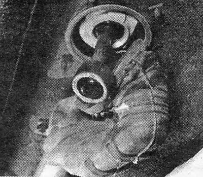
Photo 5.4. Protective cover at the base of the gear lever.
5. If it is necessary to disassemble the mechanism to replace worn parts, the locking pin should be removed from the intermediate lever and rod (see Fig.6.9).
6. Drive the rod out of the lever.
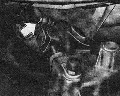
Pic. 6.6. Gear linkage coupling pinch bolt (shown by arrow)
7. To disassemble the universal joint, cut off the heads of the rivets.
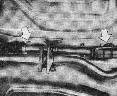
Pic. 6.7. Protective cover and cover for gear shift rod (shown by arrows)
8. Using a metal rod, drive the bushings out of the protective casing.
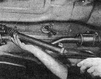
Pic. 6.8. Removing the protective cover from the gear shift rod
9. Begin assembly by filling the grooves for the bushings with lubricant and installing the bushings into the protective casing.
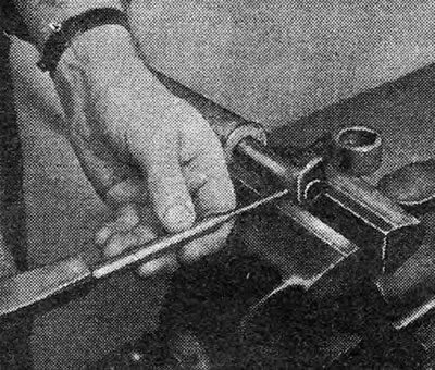
Fig.6.9. Removing the roll pin securing the linkage to the intermediate lever
10. When assembling universal joints, instead of rivets, you can install special pins with locking rings.
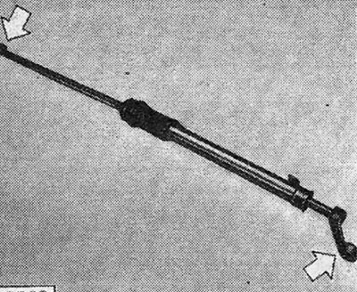
Fig.6.10. Relative position of intermediate lever and clamp (shown by arrows)
11. Connect the intermediate lever to the gear shift rod using a new pin and check that the lever is positioned relative to the clamp, as shown in Fig. b.10.
12. Install the boot and cover into the protective casing and coat the inside of the cover well with silicone grease.
13. Insert the gear shift rod into the protective casing and install it in place.
14. Adjust the gear shift linkage as indicated in the next section.
Visitor comments