
Removal
1. Disconnect the cable from the clutch release lever.
2. Disconnect the wiring from the reverse light switch (see photo).
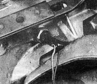
Photo 7.2. Reversing light switch wires.
3. Unscrew the clamp bolt and disconnect the gear shift rod.
4. Disconnect the speedometer drive cable from the gearbox housing by unscrewing the knurled ring or bolts securing the locking plate (depending on model).
5. Raise and support the front of the car.
6. Remove the left front wheel.
7. Disconnect the grounding bus connecting the gearbox to the machine body (see photo).
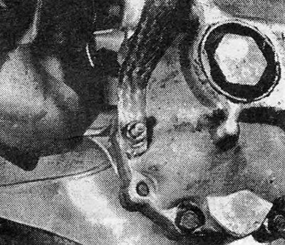
Photo 7.7. Gearbox grounding bus.
8. Remove the bracket for the long exhaust pipe from the box housing (depending on model).
9. Disconnect the anti-roll bar from the lower left suspension arm.
10. Remove the bolts securing the suspension arm support (see chapter 10). If the suspension arm and its support are suspended on the steering axle only by a ball joint, turn the arm to the side so that it is not in the way.
11. Using a suitable tool, disconnect the left drive shaft from the box (see chapter 7) (Be prepared for some oil to spill out of the box). Pull the shaft towards you and remove it from the box.
12. Remove the plug from the end cover of the gearbox.
13. Remove the opened retaining ring (see photo).
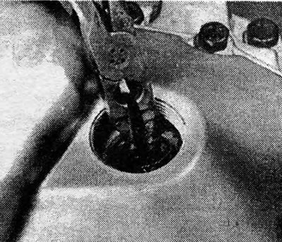
Photo 7.13. Retaining ring of the gearbox drive shaft.
Pic. 6.13. Speedometer cable and connection point of the gear shift rod to the gearbox
14. Now you will see a screw with a 12-point hole in the head, which requires a special key to remove (In principle, you can try to get by with a hex wrench) (see photo).
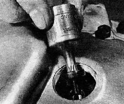
Photo 7.14. Removing the screw with a hole in the head for a 12-point head from the drive shaft.
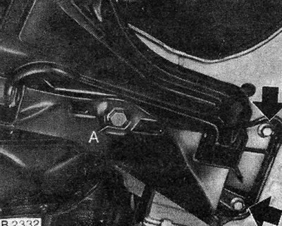
Pic. 6.14. Bolts securing the control arm support (shown by arrows) - models with a 1.3 l engine and some models with a 1.6 l engine (see chapter 10): A. Center bolt on position sleeve.
15. Unscrew and remove the screw.
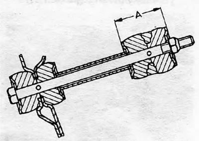
Pic. 6.15. Scheme of mounting the tip of the anti-roll bar: A = 38.0 mm.
16. As stated in Chapter 5, the manufacturer recommends using a special tool to remove the transmission drive shaft from the clutch driven disc. In order to do without a special tool, you can unscrew one of the 4 bolts securing the gear shift cover to the top of the gearbox housing and screw this bolt into the end of the drive shaft. Grasping the screw with pliers, pull the drive shaft out of the clutch driven disc (do not forget to reinstall the bolt on the gearshift cover afterwards).
17. Support the engine with a jack or hang it on a lift. Support the gearbox with a garage jack.
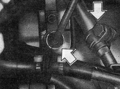
18. Disconnect the left rear support bracket from the gearbox and from the rubber cushion (see photo).
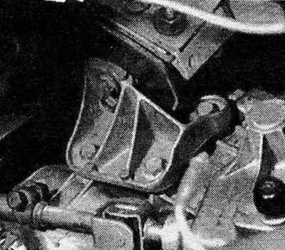
Photo 7.18. Rear left transmission support bracket.
19. Disconnect the left front support bracket from the gearbox and from the rubber cushion.
20. Move cables, wires and disconnected parts away from the box.
21. Remove the bolts securing the clutch housing to the engine.
22. Remove the bolts and remove the lower cover of the flywheel housing (facing the drive end of the motor).
23. Lower the box. This will cause the right drive shaft to fall out, so support it in advance. Pull the box out from under the car.
24. Clean the gearbox from dirt. If the box is going to be rebuilt, it should be moved to a workbench.
Installation
25. Move the box under the car and lift it on a jack in order to connect it to the engine. If you disassembled the clutch, you should center the driven disc (see chapter 5). While lifting the box, insert the right drive shaft into it.
26. Insert the flywheel flange mounting bolts and tighten them to the required torque. Reinstall the flywheel housing cover.
27. Install the front and then rear engine mounts.
28. Connect the drive shafts to the box and secure their retaining rings by placing a heavy bead against the weld bead of the hinge weld and sharply hitting the bead with a hammer (see chapter 7).
29. Install the suspension arm with support (see chapter 10).
30. Clean the threads of the lever support bolts from the old thread locking compound and apply a new compound. Insert the bolts and tighten them to the required torque (see chapter 10).
31. Connect the anti-roll bar to the suspension arm. Be careful not to overtighten the mounting bolt or nut. They must be tightened just enough to maintain the size (A), shown in Fig. 6.15.
32. Insert the drive shaft of the box into the splines of the hub of the driven clutch disc. Screw in a screw with a hole in the head for a 12-point head and install the retaining ring.
33. Install the screw plug on the end cover of the box. It is very important that the plug does not leak, so on 4-way boxes, apply sealant to the threads of the plug or wrap it with tape to seal the threaded connections. On 5-speed gearboxes, the plug has a different design and can be installed without prior preparation (see photos).
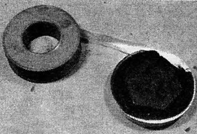
Photo 7.33A. Wrap the threads of the plug with sealing tape for threaded connections.
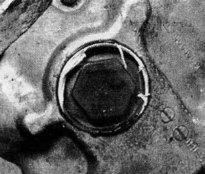
Photo 7.33B. Reinstalled transmission end cover plug.
34. Connect the grounding bus.
35. Reinstall the wheel.
36. Connect the wiring to the reverse light switch. Connect the clutch and speedometer cables.
37. Connect and adjust the gear shift rod (see sections 5 and 6).
38. Lower the car to the ground.
39. Pour oil into the box.
Visitor comments