
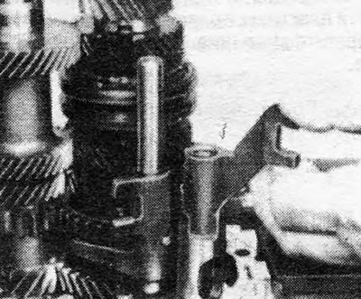
2. Manually move the 5th gear synchronizer to the engaged gear position and then, using a hex wrench, remove the bolts securing the 5th gear fork (see fig. 6.29).
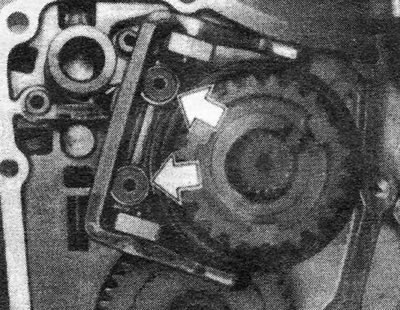
Pic. 6.29. Hex head screws securing 5th gear fork (shown by arrows) — gearbox F10.5
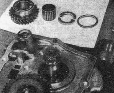
Pic. 6.30. 5th gear parts removed from the driven shaft - F10.5 gearbox
3. Remove the retaining ring from the end of the driven shaft and, using a puller, remove the 5th gear synchronizer from the driven shaft.
4. After this, you can remove the 5th gear along with its bearing, split thrust washer and thrust washer retaining ring from the driven shaft.
5. Remove the retaining ring from the end of the drive shaft and pull or press the 5th gear off the shaft. If you use a puller, be careful not to damage the drive shaft and place something under the jaws to distribute the load.
6. Using a hex wrench, remove the screws securing the locking pawl of the gear rod 5 to the intermediate plate (see fig. 6.31).
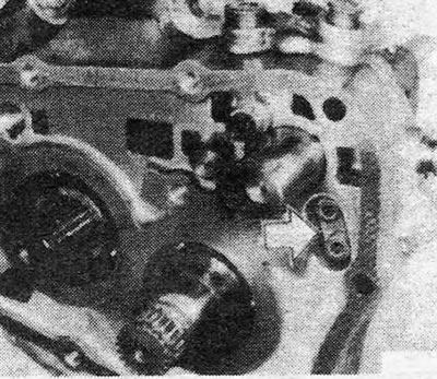
Pic. 6.31. Screws securing the 5th gear rod locking pawl (shown by arrow) — gearbox F10.5.
7. Pry off the plugs of the clamps and remove them from the intermediate plate. Pull out the springs and plungers of the clamps. Plugs damaged during removal must be replaced with new ones.
8. Move the 5th gear rod to the engaged gear position and move the 2nd gear fork so as to engage 2nd gear.
9. Using a hex wrench, remove the screws securing the locking plunger jumper. Remove the jumper and return the gears to neutral (see fig. 6.32).
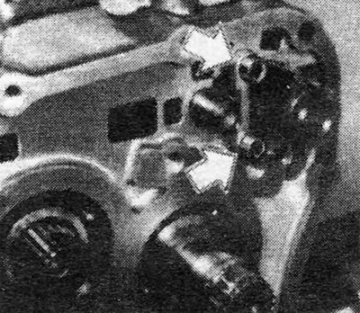
Pic. 6.32. Locking plunger jumper mounting screws (shown by arrow) — gearbox F10.5
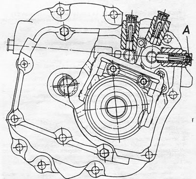
Pic. 6.33. Removing the 5th gear rod driver - F10.5 gearbox.
10. Drive out the cylindrical pins securing the 3/4 gear forks and reverse gears. Remove the forks and rods.
11. Pull the 5th gear rod driver out of the intermediate plate.
12. Remove the retaining rings holding the driven and driven shafts to the intermediate plate. After this, you can pull out the gear blocks along with the reverse idler gear, 1/2 gear fork and rod.
13. Further reassembly is carried out in the same way as described in section 8 for box F10.4. Please note that the 1st and 5th gears on the driven shaft of the F10.5 gearbox have split needle bearings.
14. The gearbox is assembled in the reverse order. Please note the following points:
- A. Secure the locking plunger jumper and the 5th gear rod pawl with new screws. The threads of these screws must be coated with thread locking compound and must be replaced after each removal.
- b. Please note that the longer plug is for the 3/4 gear retainer (see Fig.6.34).
- V. Before installing the 5th gear synchronizer on the driven shaft, it should be heated to 100°C.
- d. The threads of the end cap plug do not need to be coated with sealant.
Pic. 6.33. Removing the 5th gear rod driver - F10.5 gearbox.
Visitor comments