
2. Install the half-ring thrust washers so that their protrusions are aligned with the holes in the shaft, and secure the washers with a locking ring (see photo).
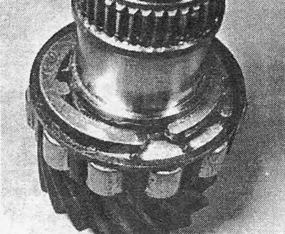
Photo 19.2A. Main drive gear bearing half-ring thrust washers
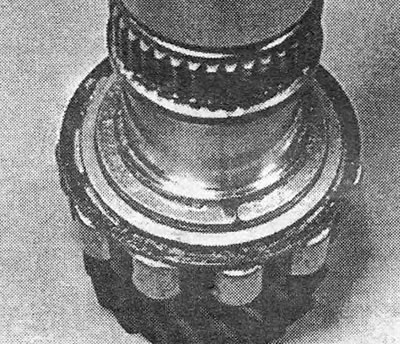
Photo 19.2B. Drive shaft thrust washers with their own retaining ring.
3. Install the split needle roller bearing (see photo).
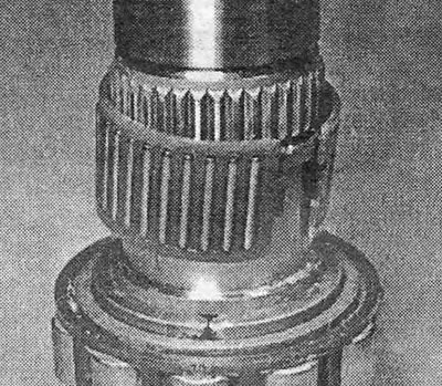
Photo 19.3.
4. Install the 4th gear (see photo).
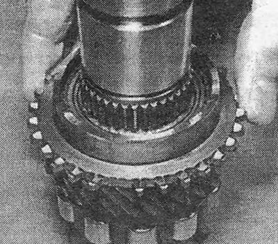
Photo 19.4.
5. Install the 4th gear cone ring (see photo).
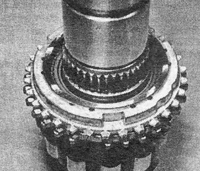
Photo 19.5.
6. Install the 3/4 gear synchronizer so that the narrow groove on its clutch is on the side away from the main gear drive gear. Drive the synchronizer along the shaft using a puller or tube resting on the synchronizer hub (see photo).
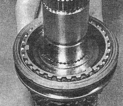
Photo 19.6.
7. Install the thrust washer (see photo).
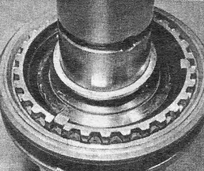
Photo 19.7.
8. Install the retaining ring (see photo).
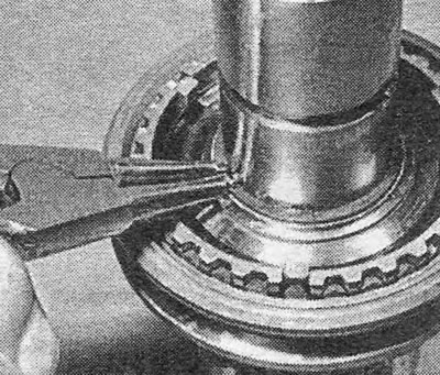
Photo 19.8.
9. Install the 3rd gear cone ring (see photo).
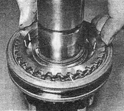
Photo 19.9.
10. Install the split needle roller bearing (see photo).
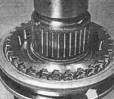
Photo 19.10.
11. Install the 3rd gear.
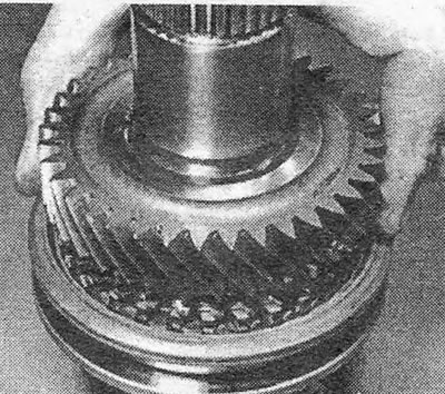
Photo 11/19.
12. Install half-ring thrust washers and secure them with a locking ring. Install the needle roller bearing (see photos).
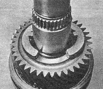
Photo 19.12A. Half-ring thrust washers.
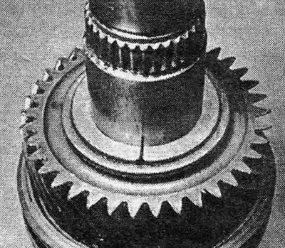
Photo 19.12V. Retaining ring of thrust washers.
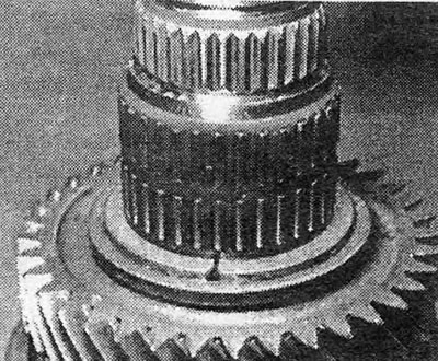
Photo 19.12С. 2nd gear needle roller bearing.
13. Install the 2nd gear.
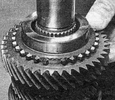
Photo 19.13. Installing the 2nd gear.
14. Install the 2nd gear cone ring (see photo).

Photo 19.14. Installing the 2nd gear cone ring.
15. Install the 1/2 gear synchronizer so that the reverse gear teeth on its clutch face the direction of the main gear drive gear. Drive or drive the synchronizer into its place on the shaft (see photo).
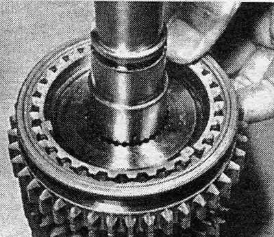
Photo 19.15. Installing 1/2 gear synchronizer.
16. Install a regular thrust washer (see photo).
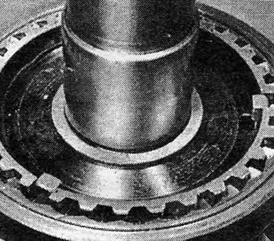
Photo 19.16. A simple thrust washer located on the 3/4 gear synchronizer.
17. Install the retaining ring (see photo).
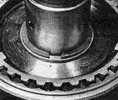
Photo 19.17. Retaining ring installed.
18. Install the cone ring of the 1st gear gear (see photo).
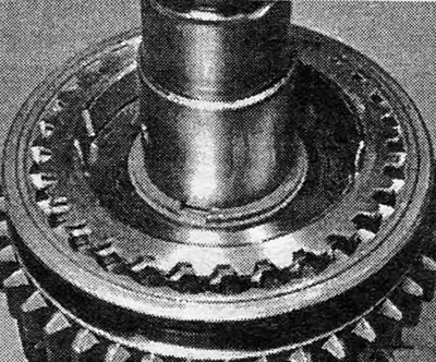
Photo 19.18. Installed 1st gear cone ring.
19. Install the split needle roller bearing, and then the 1st gear (see photos).
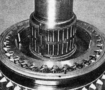
Photo 19.19A. Split needle roller bearing for 1st gear gear.
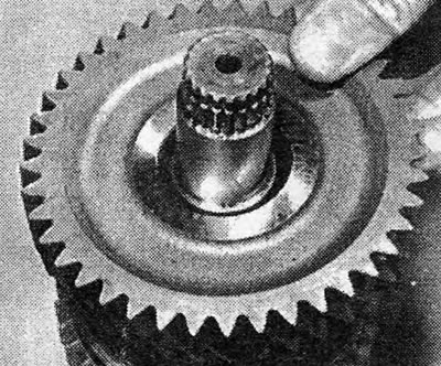
Photo 19.19В. Installing the 1st gear.
20. Install a needle-roller type thrust washer.
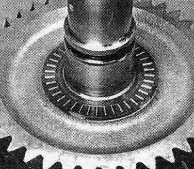
Photo 19.20. A needle-type thrust washer located on the 1st gear gear.
21. Install a regular thrust washer so that the groove on its rim is located as shown in the photo. This is to provide the necessary clearance when the driven shaft bearing retaining ring is compressed to install the gear assembly into the intermediate plate. Place the large bearing retaining ring onto the shaft (see photo).
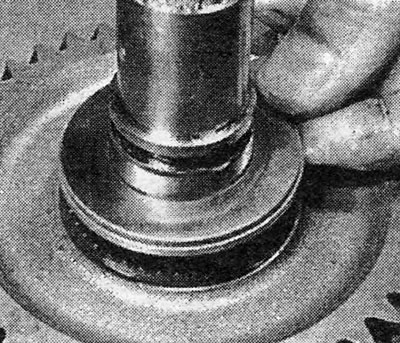
Photo 19.21A. Flat thrust washer. A groove is visible along its rim.
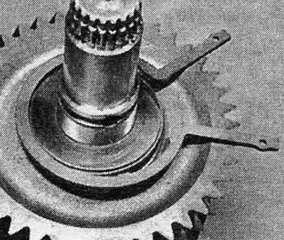
Photo 19.21B. Large driven shaft bearing retaining ring.
22. Install the ball bearing on the driven shaft so that after installation the closed side of the bearing is visible (see photo).
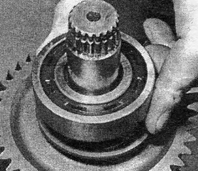
Photo 19.22. Driven shaft ball bearing.
23. Place the driven shaft bearing retaining ring in the groove on the thrust washer, compress the ends of the ring and install a temporary clamp (see section 18, paragraph 23).
24. Unclench the ends of the drive shaft retaining ring (see photo).
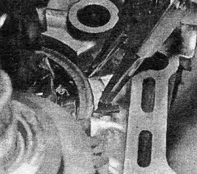
Photo 19.24. Separate the ends of the drive shaft retaining ring.
25. With someone’s help, engage the gears of the driven and drive shafts and the reverse intermediate gear, which will have to be held by hand (The groove for the gear shift fork should be on the drive gear side of the main gear) (see photo).

Photo 19.25. Installing gear blocks into the intermediate plate.
26. Install the gear blocks together with the reverse idler gear into the intermediate plate. Loosen the drive shaft bearing snap ring and remove the clamp holding the drive shaft bearing snap ring in a compressed position.
27. Install the rod and 1/2 gear fork and secure the fork to the rod with a cylindrical pin (see photos).
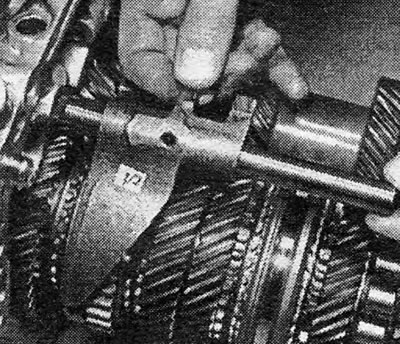
Photo 19.27A. Rod and fork 1/2 gears.
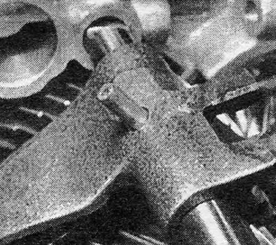
Photo 19.27B. A cylindrical pin that secures the fork to the rod.
28. Install the reverse rod and fork and secure the fork to the rod with a cylindrical pin (see photo).
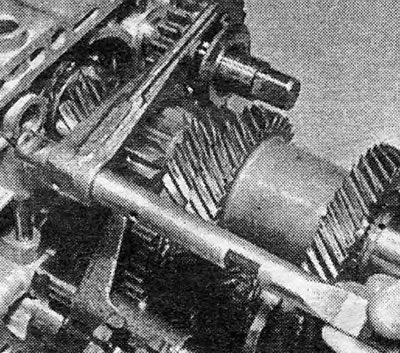
Photo 19.28. Reverse gear rod and fork.
29. Install the 5th gear rod driver into the intermediate plate.
30. Install the 5th gear rod pawl and the 3/4 gear fork and insert the rod into them (see photos).
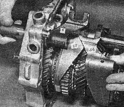
Photo 19.30A. Replaceable 5th gear rod pawl and 3/4 gear fork.
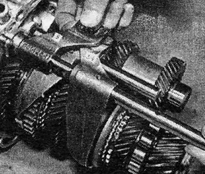
Photo 19.30B. Insert the 3/4 gear rod into the 3/4 gear fork and 5th gear pawl.
31. Fix the 3/4 gear fork on its rod with a new cylindrical pin (see photo).
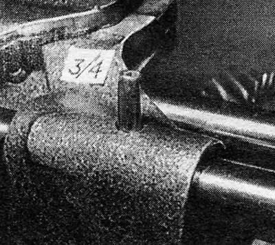
Photo 19.31. A cylindrical pin that secures the fork to the rod.
32. Insert the locking rod into the hole in the intermediate plate.
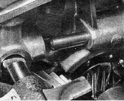
Photo 19.32. Locking rod.
33. Install the locking plunger jumper. The fastening screws of the jumper can only be tightened after the 2nd gear gear and the 5th gear rod driver have been moved to the gear positions (see photos).
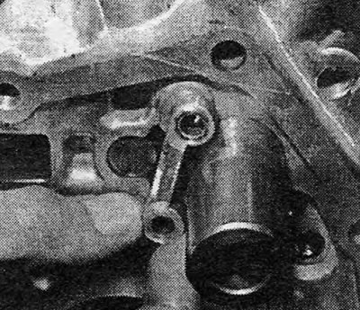
Photo 19.33A. Locking plunger jumper.
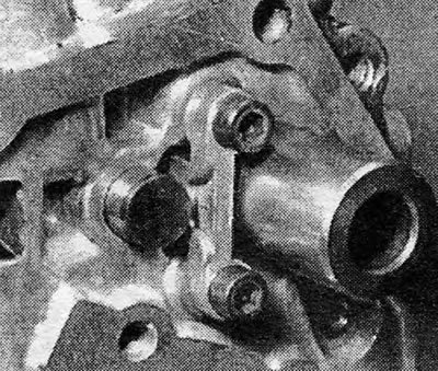
Photo 19.33B. Locking plunger jumper mounting screws.
34. Insert the 5th gear pawl into the slot on the driver and then secure the pawl to the intermediate plate with bolts (see photo).
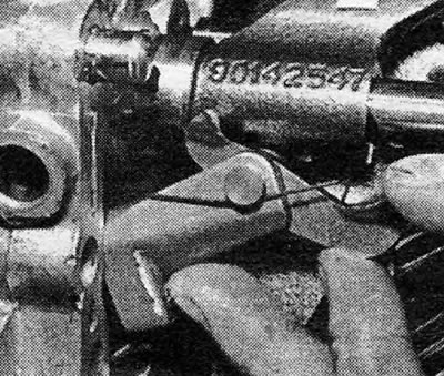
Photo 19.34A. 5th gear rod locking pawl.
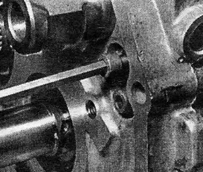
Photo 19.34B. Tighten one of the locking pawl mounting screws.
35. Insert the plungers of the clamps together with their springs into the holes in the intermediate plate (see photos).
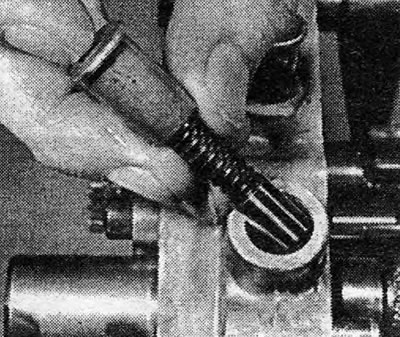
Photo 19.35A. Installing the retaining parts into the intermediate plate.
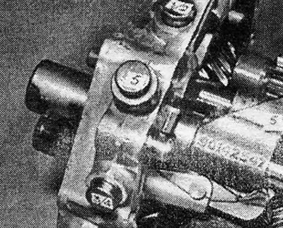
Photo 19.35B. Markings on the plugs of the clamps.
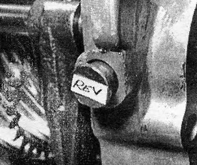
Photo 19.35С. Reverse gear lock.
36. Hammer the retainer plugs into place, noting that the 3/4 gear retainer plug is longer than the other three (see photo).
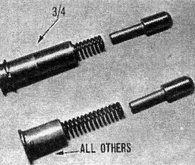
Photo 19.36. Fastener details: 1. 3/4 gear lock; 2. Locks for all other gears.
37. Install the thrust washer (one that has a central hole with flat sides) to the reverse idler gear axis. Secure the washer in place with lubricant (see photo).
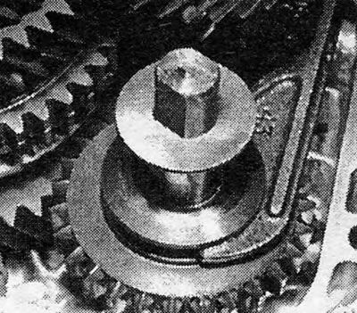
Photo 19.37. Thrust washer for the reverse idler gear axis.
38. Install a magnet (clean) into the slot intended for it on the intermediate plate (see photo).
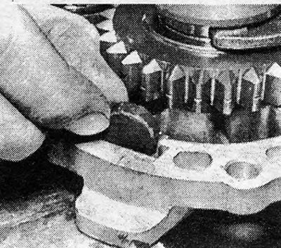
Photo 19.38. Magnet for collecting metal dust.
39. Install a new gasket on the gearbox housing flange and lower the intermediate plate into the crankcase along with the gear block (see photo).
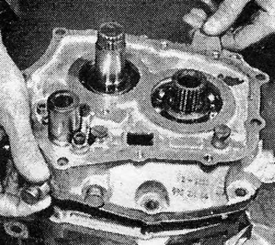
Photo 19.39. Lower the gear blocks into the gearbox housing.
40. As the gear block is lowered, engage the main gear drive gear with the driven gear (see photo).
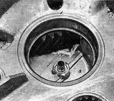
Photo 19.40. Teeth of the driven gear of the main gear.
41. Screw in the mounting bolts.
42. If the drive shaft was pulled out of the gear block, now it must be inserted into place (see photo).

Photo 19.42. Installation of the drive shaft.
43. Install the 5th gear on the end of the drive shaft and secure it with a locking ring (see photos).
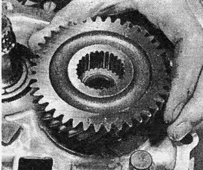
Photo 19.43A. Installing the 5th gear on the drive shaft.
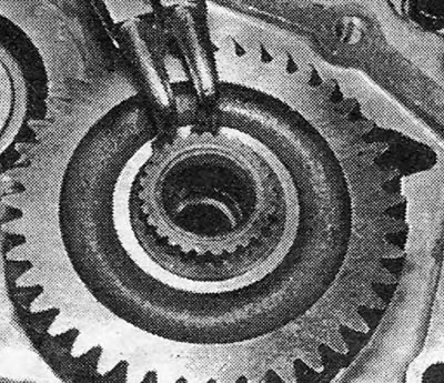
Photo 19.43B. Installing the 5th gear retaining ring.
44. Install half-ring thrust washers with a locking ring on the end of the driven shaft (see photos).
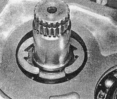
Photo 19.44A. Half-ring thrust washers.
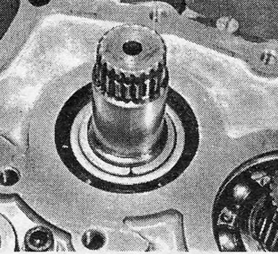
Photo 19.44B. Thrust washers and their retaining ring.
45. Install a split needle roller bearing on the driven shaft (see photo).
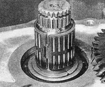
Photo 19.45. Split needle roller bearing for 5th gear gear.
46. Install the 5th gear gear on the driven shaft (see photo).
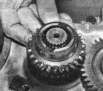
Photo 19.46. Installing the 5th gear on the driven shaft.
47. Install the cone ring of the 5th gear.
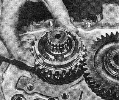
Photo 19.47. Installing the 5th gear cone ring.
48. Install the 5th gear synchronizer so that the side from which the moving keys are visible is directed towards the 5th gear gear (see photo).
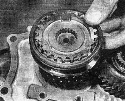
Photo 19.48. Installation of 5th gear synchronizer.
49. Install the retaining ring (see photo).
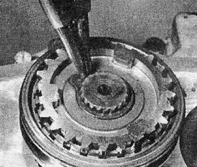
Photo 19.49. Installing the driven shaft retaining ring.
50. Move the 5th gear to the engaged position and install the fork with the hinge screw. Tighten the hex head screws (see photo).
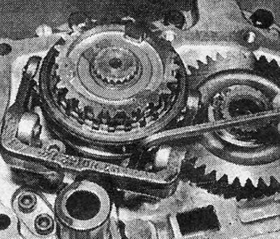
Photo 19.50. Tightening the 5th gear fork pivot screw.
51. Install the screw and retaining ring on the end of the drive shaft. The retaining ring is located in a groove deep in a recess at the end of the shaft and you will need special pliers to work it (see photos).
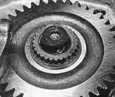
Photo 19.51A. Installing a screw with a hole in the head for a 12-point socket into the recess at the end of the drive shaft.
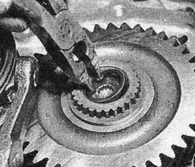
Photo 19.51B. Installing the retaining ring into the recess at the end of the drive shaft.
52. Install the end cover with a new gasket and secure it with bolts (see photos).
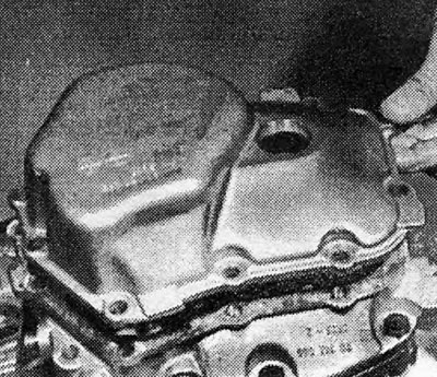
Photo 19.52A. Installing the end cover.
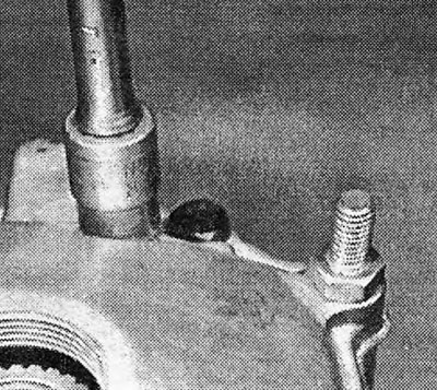
Photo 19.52B. Tightening the end cap bolts.
53. Screw the screw plug into the end cap (if filmed) (see photo).
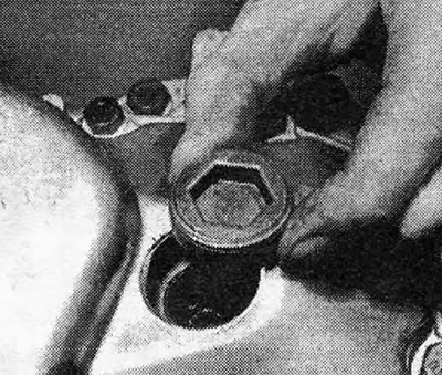
Photo 19.53. Screw in the end cap screw.
54. Install the gear shift cover with a new gasket so that the shift fingers engage with the pawls (the box must be in neutral position). Insert and tighten the mounting bolts (see photo).
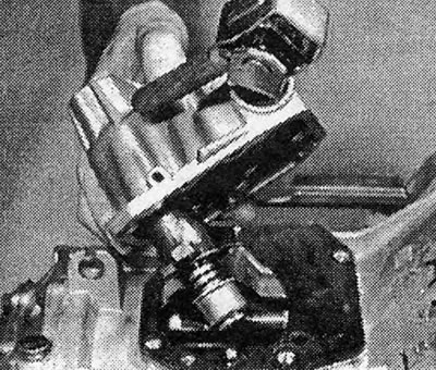
Photo 19.54. Installing the gearshift cover.
55. Bolt the final drive cover.
56. Bolt the flywheel housing cover (see photo).
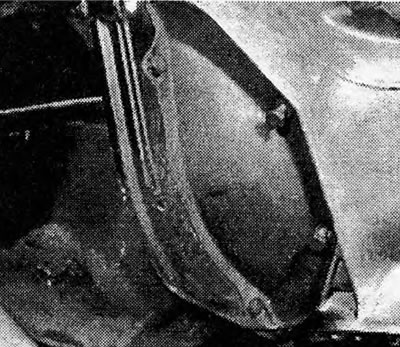
Photo 19.56. Flywheel housing cover.
57. Check that all gears are engaged (see photo).
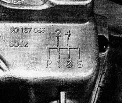
Photo 19.57. Gear shift diagram on the gear shift lever.
58. Place the box on the car and fill it with oil.
Visitor comments