


Contents: Front section ⬇ Rear section ⬇
Front section
1. Disconnect the cable from the negative terminal of the battery (see Chapter 5).
2. Remove the rear section of the center console (see below).
3. Remove the instrument panel trim strip (see Section 37).
4. Using a plastic wedge, separate and remove the decorative frame of the gearshift lever/selector niche (see accompanying illustration).
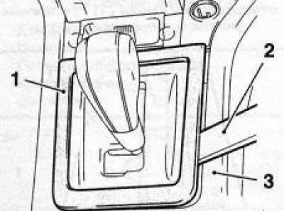
34.4 Separating the decorative frame (1) of the gearshift lever/selector housing from the centre console (1): 2. Plastic wedge
5. Remove the tray and then the front ashtray mounting housing (see Section 35).
6. Remove the cigarette lighter mounting housing (see Chapter 12).
7. On AT equipped models, remove the selector lever base cover (see Section 36).
8. Using a plastic wedge, separate the storage compartment of the console section of the instrument panel (see accompanying illustration).
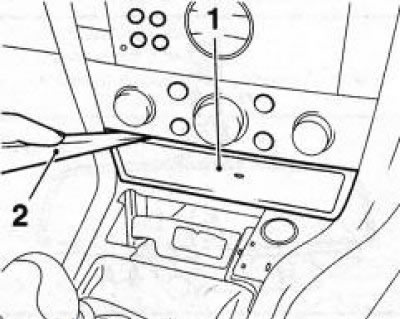
34.8 Storage compartment (1) of the console section of the instrument panel: 2. Plastic wedge
9. Remove the 2 upper screws securing the front section of the center console (see accompanying illustration).
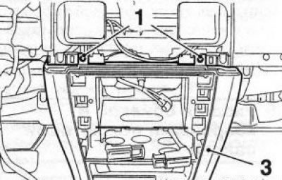
34.9 Upper screws (1) for securing the center console (3): 2. Plastic wedge
10. Loosen the inner mounting screw, pry up with a plastic wedge and remove the 4 decorative plugs on both sides of the front section of the center console (see accompanying illustration). Remove the 4 mounting screws, lift the rear of the front section slightly and pull the section backwards.
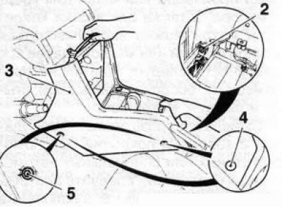
34.10 Removing the front section (3) of the centre console: 2, 5. Mounting screws; 4. Decorative plugs
11. Installation is performed in the reverse order of removal. Pay attention to the correct routing of the wiring harnesses.
Rear section
12. Remove the tray and the rear ashtray mounting housing (see Section 35).
13. Using a plastic wedge, separate the decorative panel from the rear end of the center console (see accompanying illustration). Use a wedge to pry up and separate the trim with the power take-off socket from the center console, disconnect the electrical wiring connector from the back of the socket and remove the trim.
Note: Depending on the equipment, there may be some other switches and controls installed in the rear section of the center console. Refer to Chapter 12 for removal procedures.
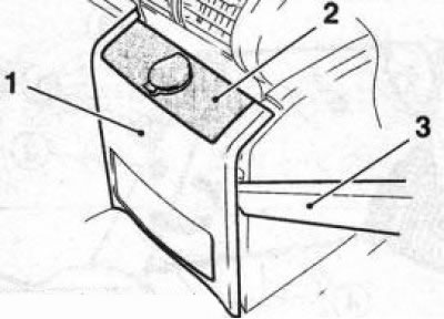
34.13 Removing the decorative panel (1) and trim (2) of the rear section of the center console using a plastic wedge (3)
14. Remove the 2 screws securing the rear section of the center console (see accompanying illustration).
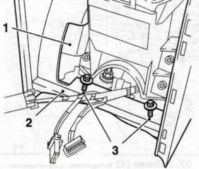
34.14 Fastening screws (3) of the rear section (2) of the center console: 1. Central armrest
15. Remove the mounting screws and remove the center armrest from the rear section of the center console (see accompanying illustration).
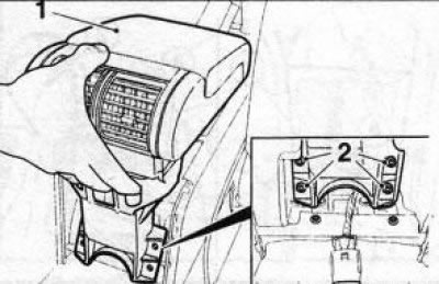
34.15 Removing the central armrest (1): 2. Mounting screws
16. Using a plastic wedge, press the latches on the right (A) and left (B) sides of the glove compartment one by one (cup holders) (see accompanying illustration) and remove the box from the center console.
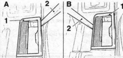
34.16 Removing the glove compartment (cup holders) (1) center console: 1. Front mounting bolt
17. Remove the front mounting screw (see accompanying illustration) rear section of the center console, apply the parking brake, pull the section back and remove it together with the air supply hose for blowing the rear space of the vehicle.
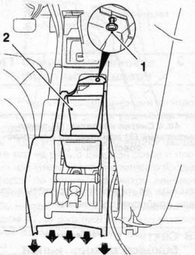
34.17 Removing the rear section of the center console - pull in the direction indicated by the arrows
18. Installation is performed in the reverse order of removal. Pay attention to the correct installation of the air supply hose and the routing of the electrical wiring harnesses.
Visitor comments