


2. Remove the lower decorative cover of the instrument panel under the steering column (see Section 39).
3. Remove the 2 screws securing the steering column lock release lever, move the lever and remove the handle from it.
4. Using a plastic wedge, remove the ignition switch cover (see accompanying illustration).
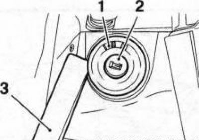
40.4 Removing the ignition switch cover (1) (2) using a plastic wedge (3)
5. Set the steering column to its lowest position.
6. Pry and remove the decorative plugs of the side mounting screws from the steering column cover (see accompanying illustration), remove the screws.
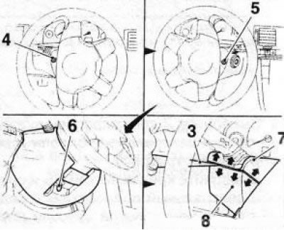
40.6 Side (4 and 5) and lower (6) screws for fastening the upper (7) and lower (8) steering column casing: 3. Plastic wedge
7. Remove the lower mounting screw, insert a plastic wedge between the upper and lower steering column covers and separate the upper cover from the lower cover (see illustration 40.6).
8. Fold the top cover up (see accompanying illustration) and disconnect it from the steering column.
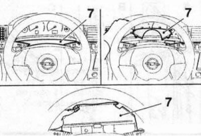
40.8 Upper cover (7) of steering column
9. Press the tabs on the sides of the lower instrument cluster trim and remove the trim together with the upper steering column cover (see accompanying illustration).
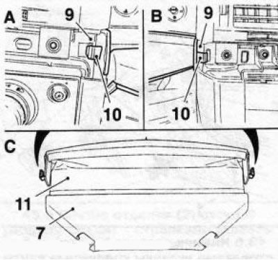
40.9 Removing the upper casing (7) from the instrument cluster (9): 10. Fixators; 11. Lower instrument cluster trim
10. Remove the 2 screws securing the lower steering column cover (see accompanying illustration), press the steering wheel lock release lever and remove the lower cover downwards, through the lever.
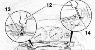
40.10 Screws (13 and 14) for fastening the lower steering column cover: 12. Screwdriver
11. Installation is performed in the reverse order of removal. Make sure that when installing the ignition switch trim, the "0" marking matches the "zero" position of the ignition key.
Text was copied from the portal [OPELBOOK]
Visitor comments