
2. Release the cable channel cover from the holders (see resist. illustration) and put it aside.
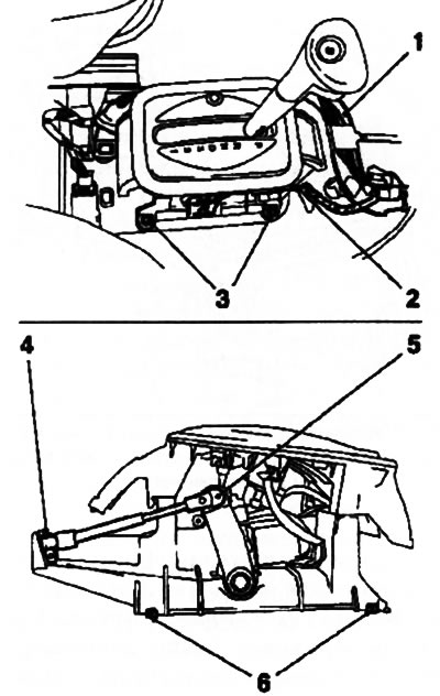
3.2. Removing the selector lever assembly: 1. Cable channel casing; 2. Wiring connector; 3, 6. Mounting bolts; 4. Rope holder; 5. Rope end
3. Disconnect the torso of the gearshift drive from the selector lever assembly, to do this, first wring out and remove the tip of the cable from the selector drive lever (see illustration 3.2), and then use a screwdriver to pull out the lock (see illustration 3.5) and release the cable from the holder on the assembly bracket.
4. Unlock and disconnect the wiring connector (see illustration 3.2), remove the 4 mounting bolts and remove the selector lever assembly.
5. If it is necessary to remove / replace the drive cable, disconnect the end of the cable from the actuating lever and release it from the holder on the gearbox (see section 2), and then pull it out of the guide rubber sleeve on the bulkhead of the engine compartment (see resist. illustration).
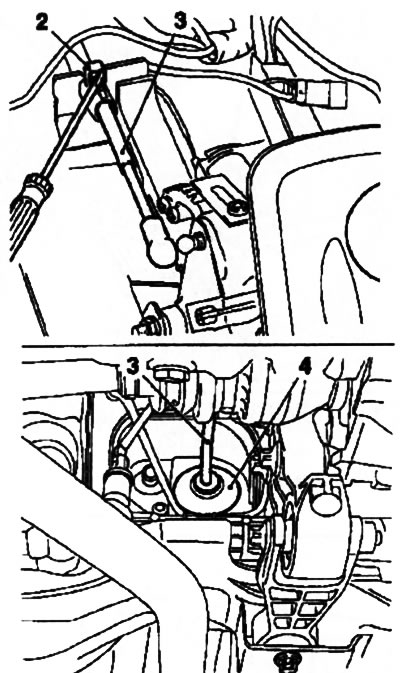
3.5. Removing the cable (3) gear change drive (models with AT): 2. Retainer; 4. Rubber guide sleeve
6. Mounting of the actuating lever is shown in resist. illustrations, if necessary, turn out alternately first the nuts, and then the bolts of the lever assembly and remove the assembly from the gearbox.
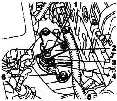
3.6. Actuator Assembly Fixing (2) (models with AT): 1, 3. Fixing nuts; 4. Fixing bracket; 5. Assembly of the executive lever; 6. Mounting bolts
7. Installation is carried out in the reverse order. Adjust drive (see section 2).
Visitor comments