
Removing
1. The gearbox can be removed in two ways: together with the engine on the subframe (see chapter 2) or separately from the engine. In the second case, special lifting devices are required - a hoist, a winch or a special transverse beam / rod, which is installed on top of the side members, and a set of rigging equipment. Opel service stations use a cross bar and a special universal kit to hold the engine in a suspended position (see chapter 10).
2. Disconnect the battery (see chapter 5), disconnect the wiring from the electronic engine control module (ECM) and take it off.
3. Disconnect the drive cable from the actuating lever and release it from the holder on the gearbox (see section 2). Disconnect the shift lever wiring connector, release the wiring harness and take it to the side.
4. Disconnect the upper oil hose from the AT, close the holes with suitable plugs.
Note: Depending on the configuration and layout of the units in the engine compartment, it may be necessary to separate and take aside some of the other lines laid on top of the AT.
5. Turn out the top bolts of fastening of transmission to the block of the engine and remove a probe tube for measurement of ATF level.
6. Hang the power package using lifting equipment (see chapter 10).
7. Install the right engine mount remover, remove the rear engine mount (see chapter 2) and remove the front suspension subframe (see chapter 10).
Note: The KM-6169 fixture must remain on the subframe - in this case it is intended for centering the AT during its subsequent installation.
8. Pry the retainers with a suitable tool and disconnect the AT fluid coolant lines (see resist. illustration). Close the holes with suitable plugs, remove traces of ATF leakage with a rag.
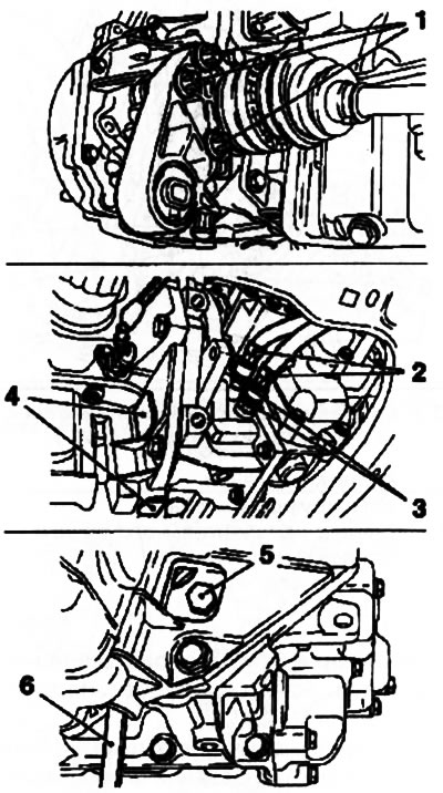
5.8. Fasteners (3) fastening lines (2) AT cooling systems: 1. Bolts of fastening of a back support of the engine; 4. Service covers; 5. Torque converter mounting bolt (total 3 pcs.); 6. Adaptation KM-911
9. Remove service covers (plugs), blocking access to the torque converter mounting bolts and the hole for installing the KM-91 tool 1 (see illustration 5.8).
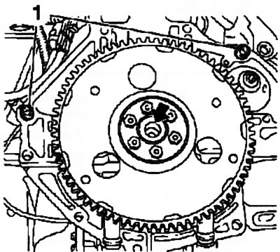
10. Turning the torque converter, alternately unscrew 3 bolts securing it to the drive disk, holding the disk from turning using the KM-911 tool, and disconnect the transformer from the disk.
11. Remove the drive shafts, including the intermediate (with appropriate equipment) (see chapter 8), while the shafts do not have to be completely removed - just disconnect them from the transmission and tie them to the load-bearing parts of the body on the bottom of the car.
12. Turn out fixing bolts and remove the left support of the power unit (see chapter 2).
13. Gradually releasing the hoist / rigging equipment, lower the power unit by approximately 5 cm - make sure that the communication lines laid from below are not pinched (hoses and wiring) and make sure that nothing prevents the removal of the box.
14. Disconnect the sensor wiring connector (see resist. illustration) and install the MKM-886-A device on the box, lifting it on a jack.
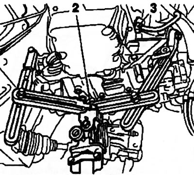
5.14. Installing the KM-886-A fixture (2): 3. Wiring connector
Note: Before using the device, carefully read the instructions for its use. Attach the box to the fixture.
15. Turn out the lower bolts of fastening of a transmission to the oil pallet, and then the lower side bolts (see resist. illustration) fastening the box to the engine, disconnect the box from the cylinder block, make sure that the transformer is separated from the drive disk, and lower it on the jack. Be careful not to drop the torque converter or damage the transmission components.
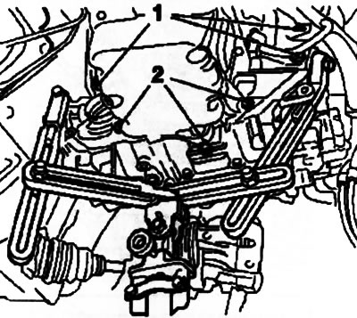
5.15. bottom bolts (2) AT oil pan mounts and side bolts (1) mounts
16. Fix the torque converter with a special tool (see resist. illustration).
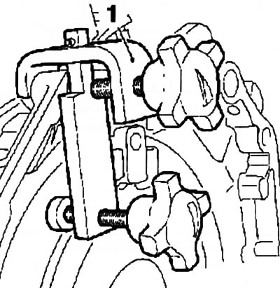
5.16. Installing the KM-6388 fixture (1) for attaching the torque converter
Installation
17. Installation is carried out in the reverse order to the dismantling of the components. Pay attention to the following points:
- a) Before installation, drive the threaded holes of the torque converter with a tap, completely removing traces of corrosion and old sealant from their turns (instead of a tap, you can use an old bolt of the appropriate size, after making a longitudinal cut in it);
- b) Check that the guide bushings are in place and lubricate with molybdenum grease the torque converter guide pin and centering bush on the crankshaft trunnion (see resist. illustration);
- c) Follow the correct installation of the transmission on the engine, tighten all fasteners with the required force;
- d) Do not forget to replace the bolts securing the torque converter to the drive disk;
- e) Replace the O-rings of the fitting connections of the ATF cooling path lines, make sure that the tubes are securely fastened;
- f) Do not forget to replace the sealing element of the ATF dipstick guide tube;
5.17. Installation locations for guide bushings (1) - the arrow shows the place of lubrication
18. Finally, fill the transmission with the required amount of fresh ATF (see chapter 1 and Section 4 this chapter) and adjust the gearshift drive (see section 2).
Visitor comments