
Removing
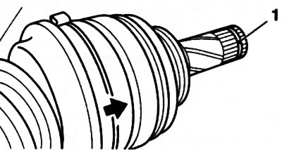
Attention: When pulling the CV joint pin of the drive shaft from the corresponding spline connection, the shaft must be pulled by the joint assembly - in no case by the shaft itself!
1. Engage neutral (RKPP) / move the selector lever to position «N» (AT).
2. Loosen the hub nut of the corresponding front wheel (see section 2).
3. If, when the wheel nuts were released, the wheels were installed in place, remove the wheels again, install the front of the car on supports. If equipped, remove the crankcase protection (see chapter 2).
4. Disconnect the right vertical stabilizer bar from the shock absorber (see chapter 10).
5. Loosen the nut (see resist. illustration) and remove the coupling bolt of the clamp securing the ball joint to the steering knuckle. Press the transverse lever down and disconnect it from the steering knuckle. If necessary, use a suitable tool to loosen the clamp.
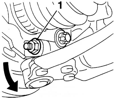
3.5. screw (1) coupling bolt of a collar of fastening of a spherical support to a rotary fist
6. Secure the drive shaft with a wire or prop so that, when removed from the hub, prevent it from hanging on the inner CV joint.
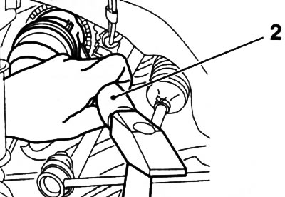
7. Pull the driveshaft shank out of the hub assembly by pulling the suspension strut outward. If it is not possible to pull out the shaft manually, install a puller on the corresponding wheel hub (see resist. illustration) and secure it with the wheel bolts. Using a puller, separate the drive shaft from the hub.
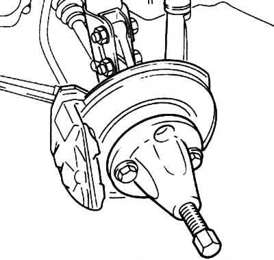
3.7. Installing the Hazet 781-5 puller to remove the drive shaft from the wheel hub
Attention: After removing the drive shaft, the wheel hub must not be loaded (use as a support), and the vehicle must not be moved, otherwise the wheel bearing may be damaged! If for any reason it is necessary to move the vehicle, be sure to insert the drive shaft element into the hub and tighten the hub nut!
8. To remove the left drive shaft from the gearbox assembly at service stations, tools Opel-KM-6003 and KM-313 are used (see resist. illustration).
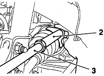
3.8. Removing the drive shaft using tools Opel-KM-6003 (2) and KM-313 (3)
9. Adaptation KM-6003 must be installed in a special groove on the CV joint housing (see resist. illustration). Make sure that when removing the drive shaft, do not accidentally damage the lock of the mounting collar and do not damage the CV joint boot.
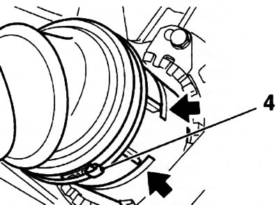
3.9. Groove (indicated by arrows) on the CV joint housing for the installation of the KM-6003 tool (the illustration shows a tripod-type CV joint): 4. Mounting collar lock
Attention: When removing the drive shaft from the crankcase of the gearbox assembly, gear oil will flow out - substitute a previously prepared container and quickly close the hole with a suitable plug!
10. Untie the drive shaft from the bottom of the car and carefully remove it from under the engine compartment.
11. On models without an intermediate shaft, the right drive shaft is removed in the same way as the left. The procedure for removing the right drive shaft together with the intermediate shaft for models equipped with diesel engines with a displacement of 1.7 liters is described in Section 4.
Installation
Note: A new hub nut and a new inner circlip will be required.
12. Thoroughly clean the splines of the shaft and the hole in the hub. Lubricate the packing lips and shaft studs with clean gear oil/ATF. Check the reliability of fixing the CV joint anthers with your clamps.
13. Remove the retaining ring from the trunnion of the inner CV joint of the drive shaft and install a new one in its place (see resist. illustration).
3.13. Groove (1) for the installation of the retaining ring - the arrow indicates the groove on the body of the double compensation CV joint
14. Remove the appropriate plug from the gearbox assembly. Carefully, being careful not to damage the oil seal, engage the inner pin of the drive shaft with the splines of the side gear of the differential - if necessary, use a mandrel to protect the oil seal (for example, Opel KM-6332). Push the shaft into the differential until the circlip snaps into place. If the retaining ring does not lock when installed by hand, you can use a plastic hammer and a brass mandrel to push the CV joint trunnion (see resist. illustration) - the mandrel must be installed in the groove on the body of the installed hinge.
3.14. Installing the drive shaft using a hammer and brass mandrel (2)
15. Enter the splined pin of the outer hinge into engagement with the spokes of the hub.
Attention: Be careful not to allow the drive shafts to sag for a long time on the anthers!
16. Tighten the hub nut (see section 2).
17. Further installation is carried out in the reverse order of removal. At the end of the operation, check the transmission oil level, if necessary, make the appropriate adjustment.
Visitor comments