


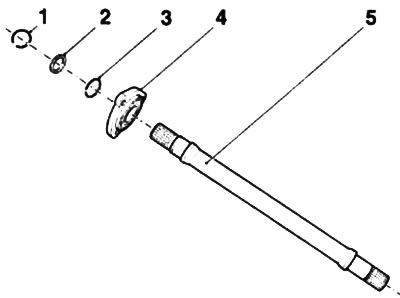
1.1. Intermediate shaft design (diesel models - 1.7 l): 1, 3. Retaining rings; 2. Sealing ring; 4. Intermediate shaft support flange; 5. Intermediate shaft
2. Each of the drive shafts is equipped with an inner and outer constant velocity joint (CV joint). Most of the models considered in this Manual are equipped with double compensation CV joints (see accompanying illustration). On models equipped with a 1.0 liter engine, internal tripod type CV joints can be installed on the drive shafts - some features of their design are discussed in Sections 5 and 6.
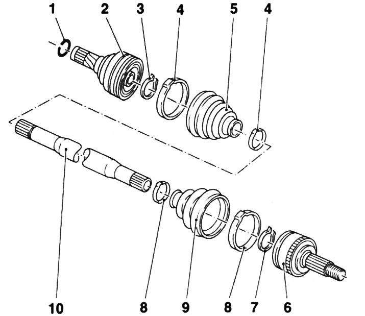
1.2. Design of the drive shaft assembly with double compensation CV joints: 1. Retaining ring; 2. Inner CV joint; 3, 7. Inner hinge retaining ring; 4, 8. Fastening clamps; 5, 9. Anthers; 6. Outer CV joint; 10. Drive shaft
[Material copied from this portal opelbook]
3. The journals of the outer joints are provided with splines, which ensure articulation with the wheel hubs. On the outer side of the hubs, the journals of the joints are fixed with large hub nuts. The inner joints are also inserted into a sliding connection with the side gears of the differential by means of splines and are fixed with the help of locking rings. Intermediate shaft (with appropriate equipment) one end of the shaft is splined into engagement with the differential side gear, the other end of the shaft is secured in the intermediate support (bracket) and is connected to the right drive shaft also using a splined connection.
Visitor comments