
Removing
Attention: When pulling the drive shaft stud out of the corresponding spline, the shaft must be pulled by the joint assembly - never by the shaft itself!
1. Engage neutral (RKPP) / move the selector lever to position «N» (AT).
Note: On models equipped with an Easytronic robotic gearbox, even when the gear is engaged, the gearbox will automatically shift to neutral before starting the engine.
2. Loosen the hub nut of the corresponding front wheel (see chapter 10).
3. Loosen the nuts of the corresponding front wheel, jack up the front of the car and place it on jack stands. Remove the wheel (see chapter «Introduction»).
Note: If your vehicle is fitted with tires with directional tread patterns, note the direction of rotation of the wheels.
If necessary, remove the crankcase protection (see chapter 2).
4. Give a nut of fastening of a tip of steering draft and by means of a special puller release the last from a rotary fist (see chapter 10).
5. Turn out a bolt of fastening of a basic arm of a flexible brake hose to a rack of a suspension bracket, release a hose from an arm (see chapter 9).
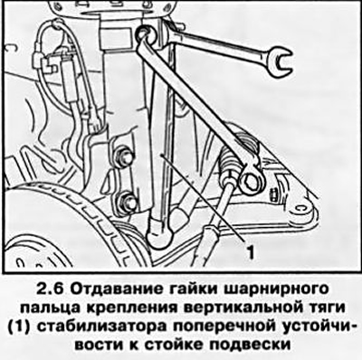
6. Holding the hinge pin with an open-end wrench by the flats, give the fixing nut and separate the anti-roll bar from the suspension strut (see resist. illustration).
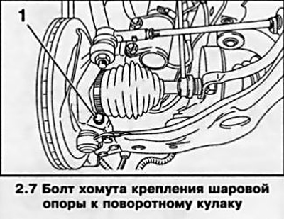
7. Turn out a bolt of a collar of fastening of a spherical support to a rotary fist (see resist. illustration) - note that the bolt is turned head first on the car.
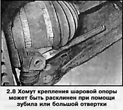
8. Use a large screwdriver or chisel to wedge the ball joint yoke (see resist. illustration).
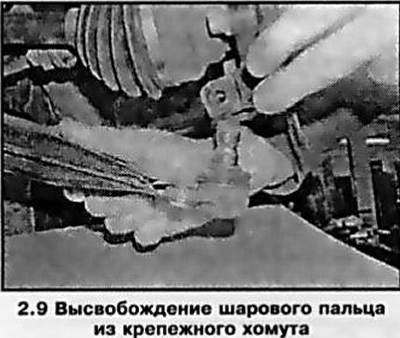
9. While moving the suspension arm down, release the shank of the ball joint pin from the mounting clamp (see resist. illustration). Move the strut to the side and release the lever - try not to damage the rubber boot of the ball joint.
10. Secure the drive shaft with a wire or prop so that when it is removed from the hub, it is not allowed to hang on the inner CV joint.
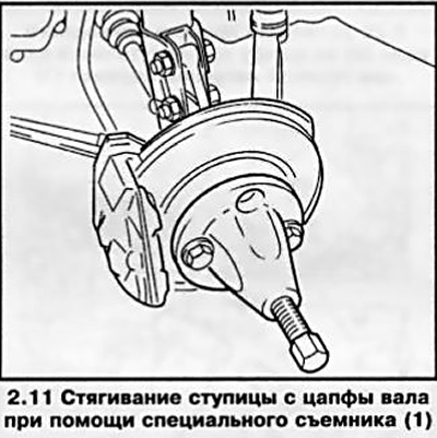
11. Pulling the hub outward, remove it from the drive shaft stub. If this fails, you can use a special puller (e.g. HAZET 781-5), bolted to the hub with wheel bolts (see resist. illustration). Move the stand aside.
12. Removing the drive shaft from the gearbox/countershaft can be done in various ways - depending on the degree of access to the connection points and the type of internal hinge (tripod/double compensation).
Attention: When removing the drive shaft from the crankcase of the gearbox assembly, gear oil will flow out - substitute a previously prepared container and quickly close the hole with an appropriate plug. If there is time and opportunity, the gear oil/ATF can be drained before performing the driveshaft removal procedure (see chapter 1).
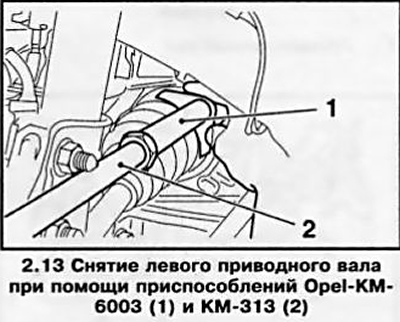
13. To remove the left drive shaft on all models covered in this manual and to remove the right drive shaft on models equipped with a 1.3L diesel engine. at service stations, devices Opel-KM-6003 and KM-313 are used (see resist. illustration). The KM-6003 device must be installed between the differential assembly housing / intermediate shaft flange and the CV joint.
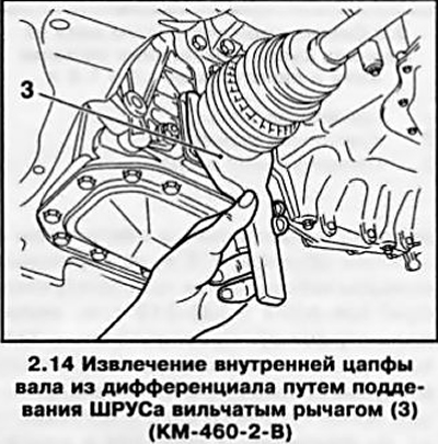
14. On gasoline models with engines of 1.4 l, 1.6 l, 1.8 l and on models with a diesel engine Z17DTL, fork tool Opel-KM-460-2-B is used to remove the right drive shaft (see resist. illustration). In the absence of the necessary tool, you can use the mount - be careful not to damage the connection elements.
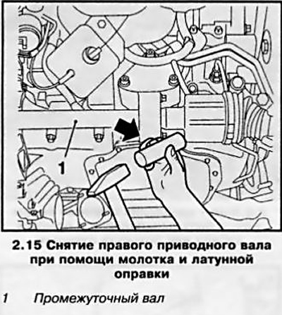
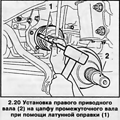
15. On models equipped with a Z17DTH diesel engine or 1.9L engine, as well as on gasoline models with 2.0L and 2.2L engines, the right drive shaft is removed from the intermediate shaft using a plastic / wooden hammer and a brass mandrel (see resist. illustration).
16. Carefully remove the drive shaft from the engine compartment.
Attention: Lowering the vehicle to the ground with even one drive shaft removed is fraught with damage to the wheel bearings!
Installation
Note: A new hub nut and a new inner circlip will be required.
17. Remove the retaining ring from the drive/intermediate shaft pin and install a new one in its place.
19. Thoroughly clean the splines of the shaft and the hole in the hub. Lubricate the packing lips and shaft studs with clean gear oil/ATF. Check the reliability of fixing the CV joint anthers with your clamps.
20. On models equipped with double compensation internal CV joints, first carefully, being careful not to damage the oil seal, engage the internal pin of the drive shaft with the splines of the side gear of the differential / countershaft - if necessary, use a reference clutch to protect the oil seal. Push the shaft into the differential until the retaining ring snaps into place, for which use a hammer and a brass mandrel - the mandrel must be installed on the thickening of the end of the installed hinge (see resist. illustration). Enter the spline pin of the outer hinge into engagement with the spokes of the hub.
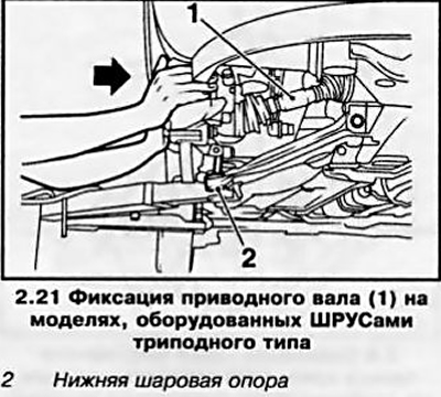
21. On models equipped with tripod-type internal joints, you must first engage the drive shaft with the splines of the hub, and then carefully engage the pin of the inner CV joint. Then, pressing on the brake disc (see resist. illustration), push the drive shaft until the circlip snaps into place, being careful not to damage the lower ball joint.
22. Further installation is carried out in the reverse order of removal.
Visitor comments