
2. The right and left drive shafts are equipped with inner and outer constant velocity joints (SHRUS). Depending on the model, tripod-type CV joints or double compensation joints can be installed on the inner end of the shaft. The design of the drive shafts is shown in Ref. illustrations.
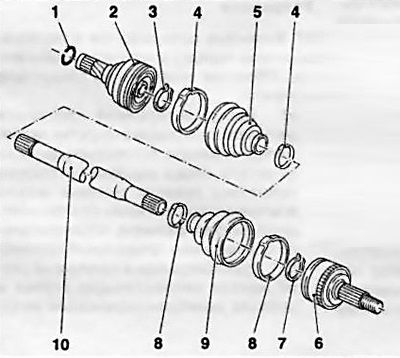
1.2a Design of the drive shaft assembly with double compensation CV joints
1 Retaining ring
2 Inner CV joint
3, 7 Inner circlip of hinge
4, 8 Mounting straps
5, 9 Dusters
6 Outer CV joint
10 Drive shaft
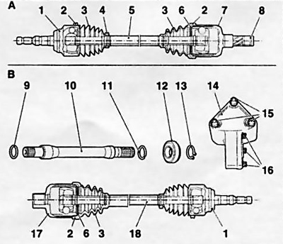
1.2b Assembly design of drive shafts with an internal tripod type CV joint and an intermediate shaft
1 outer CV joint (double compensation)
2, 4 Mounting straps
3 Anthers
5 Left drive shaft
6 Hinge retaining ring
7 Inner CV joint of tripod type
8, 11, 13 Retaining rings
9 O-ring
10 Intermediate shaft
12 Support bearing of intermediate shaft
14 Intermediate support
15 Mounting bolts for intermediate support
16 Fixing bolts of the intermediate shaft flange
17 Inner CV joint of tripod type (with slots for intermediate shaft)
18 Right drive shaft
3. The trunnions of the outer hinges are equipped with splines that provide articulation with the wheel hubs. On the outside of the hubs, the hinge pins are fixed with large hub nuts (see chapter 10). The internal hinges are also slotted into a sliding connection with the side gears of the differential and are fixed with locking rings. intermediate shaft (with appropriate equipment) one of its ends is splined with the side gear of the differential, the other end of the shaft is fixed in the intermediate support (bracket) and is connected to the right drive shaft also using a spline connection.
Visitor comments