
Note: Depending on the brand of engine and vehicle model, the suspension of the power unit can be carried out by means of three or four supports.
Examination
1. The engine is rigidly connected to the transmission assembly and has a common suspension with it, which is made in the form of a subframe and 4 supports - the right and left supports are attached to the side members, and the front and rear supports are attached to the subframe. The general layout of the suspension supports of the power unit is shown in resist. illustrations. Depending on the model, the appearance and attachment points of the supports may differ.
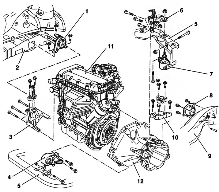
18.1. The general schematic diagram of the location of the suspension mounts of the power unit on Opel models: 1. Right support; 2. Frame; 3. Bracket right support; 4. Front support; 5. Beam subframe; 7. Torque damper; 8. Left support; 9. Subframe; 10. Transmission support; 11. Engine; 12. Transmission
2. If necessary, in order to ensure freedom of access, jack up the front of the car and place it on props. If equipped, remove the crankcase protection.
3. Check up a condition of rubber pillows of support. In case of detection of cracks, delaminations, separation from the metal substrate, signs of rubber hardening, etc. defects, replace the support.
4. Using a torque wrench, check the tightening forces of the fasteners of the supports.
5. Levering the mount, check the supports for signs of excessive play - if necessary, ask an assistant to rock the unit in different directions and observe the behavior of the supports. The backlash present in new components leads to rapid wear of the bearings. Replace defective components.
Replacement
Right support
6. To remove the right support, it is necessary to install special tools and unscrew the bolts securing the support to the side member and to the engine bracket (see Section 5).
Left support
7. To remove the left support on the service station, the same set of tools is used as for removing the right (see Section 5). It is also possible to use a jack or winch-type lifting equipment.
8. The left support is installed in the niche of the side member and is attached to the bracket fixed on the transmission through an adapter.
9. To remove the support, you must first unscrew the 2 bolts securing the adapter to the bracket (see resist. illustration), and then 4 bolts (one bolt is not shown in the illustration) fastening the support to the spar. Remove the support together with the adapter. If necessary, remove the 3 bolts and remove the mounting bracket from the transmission.
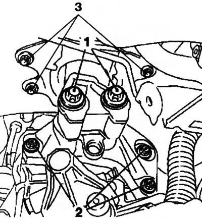
18.9. Left engine mount bolts: (on the example of the Z12XE engine): 1. Fixing the support adapter to the bracket; 2. Attaching the bracket to the transmission; 3. Fastening the support to the side member
Note: Diesel engines may require removal of the fuel filter to gain access to the support (see chapter 1).
10. If necessary, to separate the adapter from the support, secure it in a vise (see resist. illustration) and unscrew the single bolt threaded through the center of the support pad.
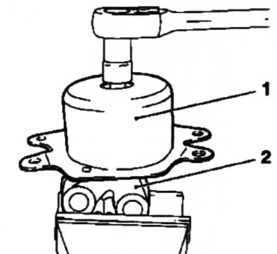
18.10. Separate the left support if necessary (1) from adapter (2) (Z12XE engine)
11. Installation is carried out in the reverse order. Make sure all fasteners are tightened to the correct torque.
Front/rear supports
12. When removing the front (with appropriate equipment) and rear supports, it is imperative to unload them. To do this, you can use a trolley jack, a winch-type lifting device, or a special MKM-883 kit for hanging the power plant (see Section 19).
13. When lifting the power unit, be careful - do not load the exhaust system, if necessary, disconnect the exhaust pipe of the exhaust system (see chapter 4).
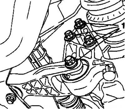
14. To remove the front support (see resist. illustration) first unscrew the 2 bolts of its fastening to the power unit, and then loosen the nut and remove the axial bolt of the support.
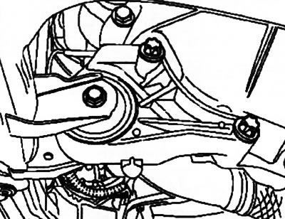
18.14. Front engine mount
15. Mounting of the rear support may be different depending on the engine model. Mounting options are shown in resist. illustrations. Turn out corresponding bolts and remove a support.
18.15a. Bolts of fastening of a back support of the Z14XE engine | 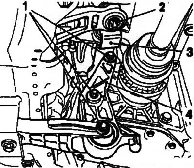
18.15b. On these models, it is additionally necessary to unlock the guide (3) gear lever and move it to the side (Z18XE engine): 1. Bolts of fastening of a back support; 2. Retainer; 4. Rear support mounting bracket |
16. Check the condition of all support components. Replace worn and damaged parts.
17. Installation is made in an order, the return to removal, tighten fixing bolts and nuts with the demanded effort. Lower the car to the ground.
Visitor comments