
Z10XE engines (P) /Z12XE/Z14XEP
2. Remove the oil pan (see Section 12) and remove the timing chain (see Section 8).
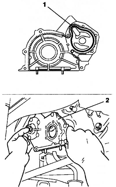
3. Remove the 6 bolts and remove the oil pump cover, and then remove the inner and outer rotors (see resist. illustration).
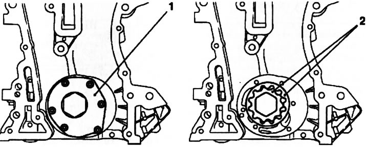
13.3. Lid (1) and rotors (2) oil pump (Z10XEP engine)
4. Clean all mating surfaces before installation. Installation is carried out in the reverse order.
Engines Z14XE/Z16XE/Z18XE
Attention: On Z18XE engines, after removing the toothed belt, it is necessary to hang the power unit using a set of tools MKM-883 and remove the tools for removing the right engine support (see Section 5).
5. Remove the toothed belt tensioner and the left toothed belt guide roller (see Section 8).
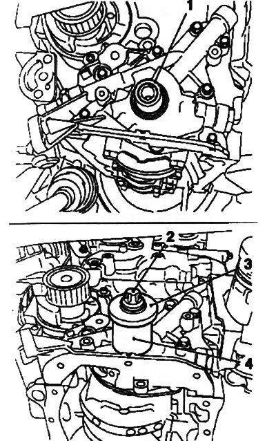
6. Remove the oil pan (see Section 12), unscrew the 3 fixing bolts and remove the oil pickup (see resist. illustration).
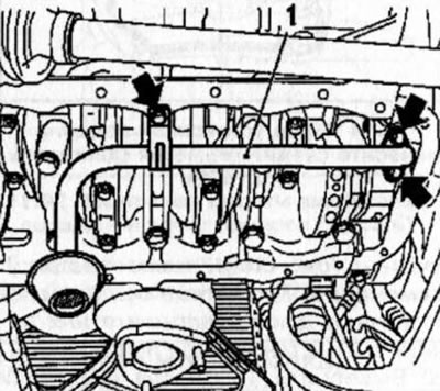
13.6. The arrows indicate the oil intake bolts (on the example of the Z18XE engine)
7. Remove gears (see Section 5) and toothed belt drive wheel.
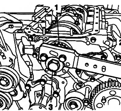
Note: To remove the wheel, it is necessary to block the flywheel from turning in the same way as when removing the crankshaft pulley (see Section 5). Turn out 2 fixing bolts and remove the rear casing of the timing drive (see resist. illustration).
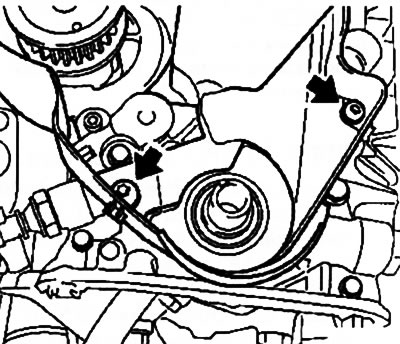
13.7. bolts (indicated by arrows) rear timing cover mounting (on the example of the Z16XE engine)
8. Disconnect the oil pressure sensor wiring connector, remove the 7 mounting bolts and remove the oil pump (see resist. illustration). Using a suitable tool, carefully, so as not to damage the seating surfaces, remove the crankshaft front oil seal.
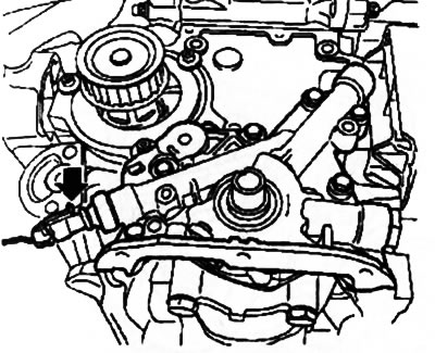
13.8. Oil pump (the arrow shows the oil pressure sensor) (on the example of the Z18XE engine)
9. Before installing the oil pump, clean all mating surfaces of sealant residue and pre-thread all holes.
10. Lubricate the surfaces of the new crankshaft oil seal with silicone grease (white color) fill it into the seat and press it in using a special tool (see resist. illustration) on the crankshaft.
13.10. Installing the oil pump seal (on the example of the Z18XE engine): 1. Protective sleeve; 2. Bolt; 3. Washer or pulley of multirib belt; 4. Device KM-6010
11. Installation of other removed components is made in an order, the return to an order of their removal.
Z16SE engine
12. The oil pump of this engine is the same design as on the Z14XE / Z16XE / Z18XE engines, and the procedure for performing this procedure is completely the same as described above for these engines. The differences relate only to the appearance of some parts and their location, which is caused by the design features of the engine with the SOHC gas distribution system.
Note: To install a new oil pump seal, use the KM-417 tool.
Z13DT engine
13. The lubrication system of this engine is shown in Ref. illustrations - the oil pump is built into the cover of the timing gear drive.
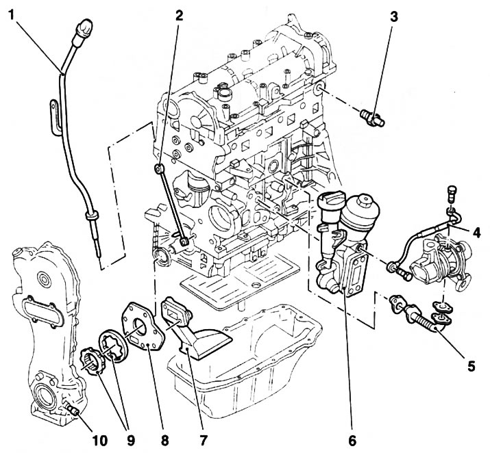
13.13. The general arrangement of the Z13DT engine lubrication system: 1. Oil dipstick with guide tube; 2. Oil pipeline; 3. Oil pressure sensor; 4. Turbocharger oil supply line; 5. Turbocharger oil return line; 6. Oil filter housing with heat exchanger and oil filler neck; 7. Oil intake; 8. Oil pump cover; 9. Oil pump rotors; 10. Safety valve
14. To remove the pump, remove the timing cover (see Section 8), unscrew the 2 bolts, separate the oil pickup from the cover, remove the seal (see resist. illustration), remove the oil pump cover and remove the outer and inner rotors.
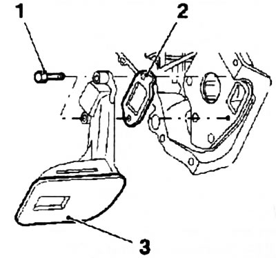
13.14. Mounting bolts (1) and sealing gasket (2) oil intake (3) Z13DT engine
Y17DT engines (L) /Z17DTH
15. Remove the oil pan (see Section 12) and toothed timing belt (see Section 8).
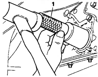
16. Remove the oil pump gear, holding it from turning with a socket wrench (see resist. illustration).
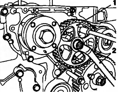
13.16. Gear (1) oil pump (motors Z17DTL/H): 2. Ring wrench
17. With the help of special devices (see resist. illustrations) Remove the timing drive gear.
13.17a. Holding the drive wheel (1) against turning with KM-662-C tool (2) unscrew the fixing bolt (3) (Z17DTH engine) | 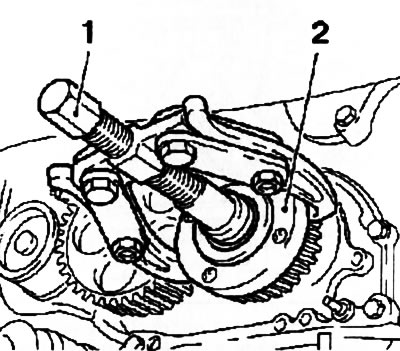
13.17b. Removing the pinion (2) timing drive using tool KM-161-B (Z17DTH engine) |
18. Turn out 9 fixing bolts and remove the case of the oil pump (see resist. illustration).
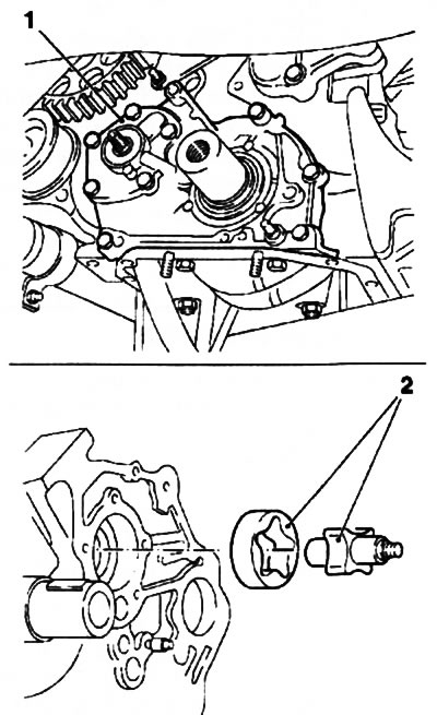
13.18. Lid (1) and rotors (2) oil pump (motors Z17DTL/H)
Attention: The bolts have different lengths - remember the order in which they are placed! Then remove the oil pump rotors.
19. Using a suitable tool, carefully so as not to damage the seating surfaces, remove the crankshaft and oil pump seals (see resist. illustration).
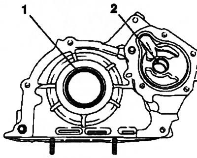
13.19. Crankshaft seals (1) and oil pump (2)
20. Clean all mating surfaces before installation. Apply sealant (black color) on the oil pump housing, replace the pump seal, insert the rotors, install the housing (see resist. illustration) and tighten the fixing bolts to the required torque (see specs).
13.20. Chassis Installation (2) oil pump (Z17DTH engine): 1. Oil pump gasket
Attention: The tightening of the bolts must be completed no later than 10 minutes after applying the sealant!
21. Lubricate the surfaces of the new crankshaft and oil pump seals with silicone grease (white color) and using the KM-656 and KM-657 fixtures, install them into the seating sockets - tap the seals until they stop (see resist. illustrations). When installing the gear wheel, pay attention to the position of the edge of the mounting hole.
13.21a. Adaptation KM-656 (1) for installing the crankshaft seal | 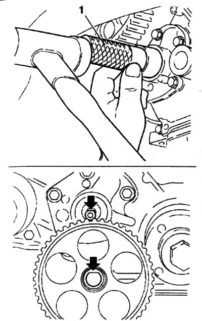
13.34b. Installing the oil pump gear (arrows show the position of the edge of the mounting hole): 1. Tool KM-657 for installing the oil pump seal |
22. Installation of other removed components is made in an order, the return to an order of their removal.
Visitor comments