
Z10XE engines (P) /Z12XE/Z14XEP
1. Remove the multirib belt cover and (with appropriate equipment) crankcase protection (see Section 5).
2. Drain the engine oil from the oil pan (see chapter 1), replace the gasket and tighten the drain plug to the required torque (see specs).
3. Disconnect the connector of the electrical wiring of the lambda probe of the catalytic converter and release the exhaust tract of the exhaust gas system from the two damping holders. Loosen the 3 nuts and disconnect the system downpipe from the catalytic converter. Using improvised materials (e.g. wire), tie it to the left subframe beam.
4. Turn out 3 bolts of fastening of the pallet to transmission (see resist. illustration), and then 16 more bolts (on ZIOXE engines (P) - 14 bolts) mountings to the engine and remove the pan.
12.4. bolts (1) mount the pallet to the transmission (on the example of the Z10XEP engine)
5. Before installing the pallet, clean all mating surfaces from the remnants of old gaskets. Install all removed components in the reverse order of their removal, do not forget to replace all gaskets. When installing the pallet, tighten all the fixing bolts by hand, and then tighten them with the required force (see specs).
Z14XE/Z16SE engines
6. Disconnect the wire from the negative terminal of the battery (see chapter 5).
7. Raise the car on a lift, drain the engine oil from the crankcase (see chapter 1). Before screwing in the drain plug, be sure to replace the gasket.
8. Remove the multirib belt cover (see Section 5). Disconnect lambda probe wiring and exhaust system (see chapter 4).
Note: Only the front of the system can be released from the holders and detached. In this case, it must be tied to the supporting parts of the car with a wire.
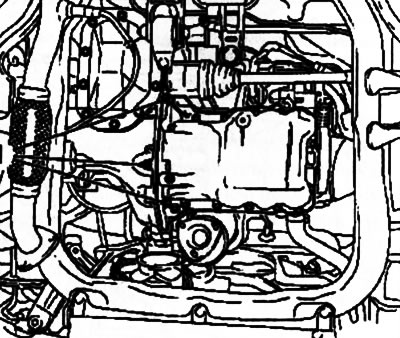
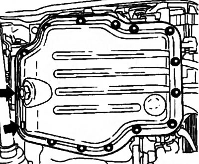
9. Remove the 2 rubber plugs and unscrew the ones indicated on the resist. illustration bolts securing the pan to the transmission and to the oil pump, and then 12 bolts to the engine. Using a suitable tool, pry and separate the oil pan.
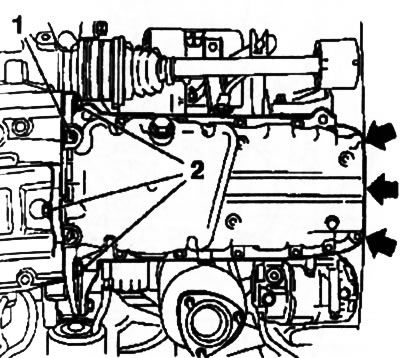
12.9. Oil pan (Z16SE engine) - the arrows indicate the bolts of the pan to the oil pump: 1. Rubber plugs; 2. Transmission mounting bolts
10. Before installing the pallet, clean all mating surfaces of sealant residues and pre-thread all holes.
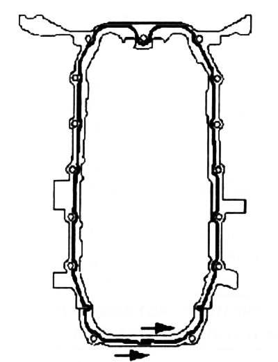
11. Apply a bead of sealant (gray color) 2.5-3.5 mm thick on the surfaces indicated on the resist. illustration and put the pallet back in place.
Attention: Installation must be completed no later than 10 minutes after applying the sealant!
12. Install the remaining components in the reverse order of their removal.
Z18XE engine
13. In principle, the procedure for removing the oil pan on this engine is exactly the same as on the Z14XE / Z16SE engines (see above). But due to the peculiarities of the engine layout, additional operations are required to free access to the pallet.
14. Remove the rear and then the front engine mounts (see Section 18).
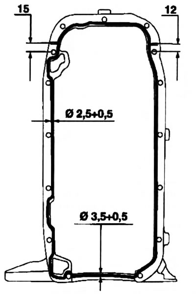
12.14. Apply fresh sealant before installing the pan (Z16SE engine)
15. Hang the engine using a set of special equipment MKM-883 or using other winch-type lifting equipment (see Section 19). Remove right engine mount (see Section 5).
16. Using the installed equipment, raise the engine to a sufficient height to access the sump and remove the sump.
17. Installation is carried out in the reverse order.
Z13DT engine
18. Carry out the operations described for this engine in Section 8 up to and including the disconnection of the catalytic converter from the turbocharger (paragraphs 86-94).
Note: It is not necessary to set the TDC position and remove the crankshaft pulley.
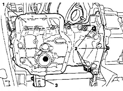
19. Disconnect the oil level sensor wiring. Turn out 5 fastening bots and remove the reinforcing element (see resist. illustration).
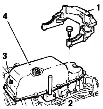
12.19. Removing the pallet (4) engine crankcase Z13DT: 1. Reinforcing element; 2. Tool KM-J-37228; 3. Fixing nut
Note: Mounting bolts have different lengths, note or mark their installation position.
20. Turn out 13 bolts and 2 nuts of fastening of the pallet, use tool KM-J-37228 (see illustration 12.19), separate and remove the pan from the engine.
21. Before installing the pallet, clean all mating surfaces of sealant residues and pre-thread all holes.
22. Apply a bead of sealant (Locktite 5900) 2.5-3.5 mm thick on the surfaces indicated on the resist. illustration and put the pallet back in place.
12.22. Apply fresh sealant before installing the pan (Z13DT engine)
Attention: Installation must be completed no later than 10 minutes after applying the sealant!
23. Install the remaining components in the reverse order of their removal.
Y17DT engines (L) /Z17DTH
24. Disconnect the cable from the negative terminal of the battery, remove the dipstick for measuring the oil level, raise the car on a lift and remove the multirib belt cover (see Section 5).
25. Remove the oil filter, drain the engine oil from the oil pan (see chapter 1), Be sure to replace the sealing washer on the drain plug.
26. Loosen the 3 nuts and disconnect the exhaust pipe from the catalytic converter (see chapter 4). Take the exhaust tract to the side and tie it to the load-bearing parts of the body with a wire. Get help from an assistant if necessary.
27. Having unscrewed 2 bolts and disconnect the tube of the dipstick for measuring the level of impellent oil.
28. Turn out 15 bolts of fastening of the bottom part of the pallet (see resist. illustration) and using the right tool (e.g. with spatula or tool KM-J-37228) pry and separate it from the top of the pallet.
12.28. Bolts of fastening of the lower part of the oil pan (Z17DTH engine)
29. To remove the top of the crankcase on the Z17DTH engine, it may be necessary to remove the front engine mount (see Section 19).
30. Disunite a socket of electroconducting of the gauge of measurement of level of engine oil. Turn out 14 bolts of fastening of the top part of the pallet to the block of the engine.
Note: Mounting bolts have different lengths, note or mark their installation position.
31. Turn out 4 bolts of fastening of the top part of the pallet to transmission (see resist. illustration) and, using a suitable tool, separate the sump from the engine block. Next, remove the 2 bolts and separate the intermediate support of the drive shaft. Remove the tray.
12.31. bolts (2) fixing the top of the pallet (1) to transmission: 3. Driveshaft intermediate bearing
32. Before installing the pallet, clean all mating surfaces from the remnants of old gaskets. Install all removed components in the reverse order of their removal, do not forget to replace all gaskets. The top and bottom of the pallet is installed on the sealant (gray color).
Visitor comments