
2. Follow the correct sequence when removing bearing caps. The fasteners of the covers should be released evenly, in a spiral from the edges inward, in several steps, 1-0.5 turns per approach. On engines whose camshafts are mounted on bearings cast directly into the cylinder head, special care must be taken when loosening the fasteners and removing the bearing caps.
Careless handling can damage the camshaft bearings or the bearing cap. If at least one cover is broken, you will have to change the entire head of the block - in the manufacture of covers, they are processed together with the head and are not supplied to the spare parts market individually! Installation and tightening of the fasteners of the covers is carried out in the reverse order of their removal.
Z10XE engines (P) /Z12XE/Z14XEP
Removing
3. Set the piston of the first cylinder to the TDC position and loosen the timing chain by pulling the chain tensioner and fixing it with the KM-955-1 tool (see Section 6).
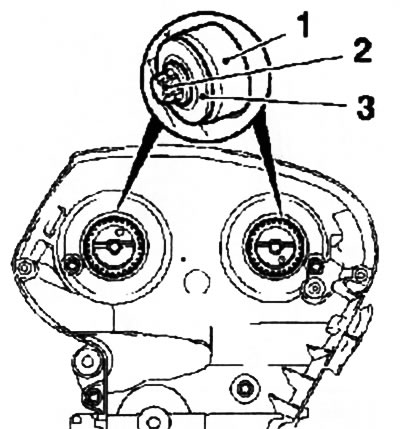
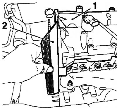
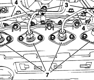
4. Having unscrewed 2 fixing bolts, remove the top rail (see resist. illustration) timing chains. Holding the camshafts from turning with an open-end wrench by the hexagonal part of the shaft, unscrew the fixing bolts and remove the camshaft sprockets.
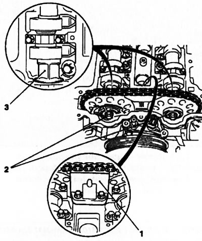
10.4. Removing camshaft sprockets (on the example of the Z14XEP engine): 1. Upper chain guide; 2. Mounting bolts for camshaft sprockets; 3. Hexagonal part of the camshaft
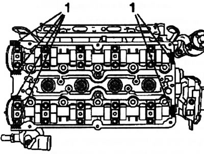
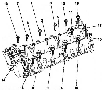
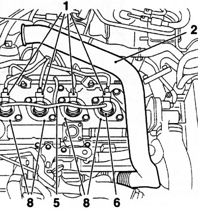
5. Please note - all upper camshaft bearing caps have their own number (see resist. illustration). 1, 3, 5, 7, 9 - exhaust valve shaft and 2, 4, 6, 8, 10 - intake valve shaft.
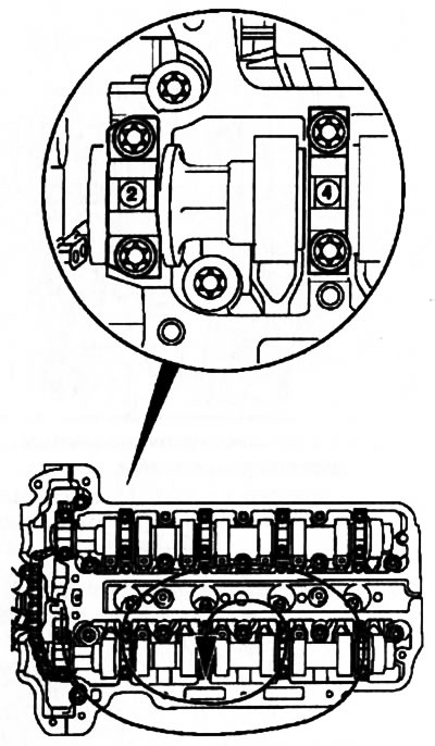
10.5. The order of turning out the fixing bolts of the upper covers of the bearings of the camshafts (on the example of the Z14XEP engine)
Note: For 3-cylinder engines there are no bearing numbers 9 and 10 respectively.
Unscrew the fixing bolts of the exhaust camshaft support bearing caps in the sequence shown, remove the caps and remove the shaft. Remove the intake camshaft in the same manner.
6. Prepare 16 small clear plastic bags or clean plastic cups and label them according to the number of valves. Using the tools, remove the pushers from the head and place them in the appropriate cups.
Note: To prevent oil leakage from the hydraulic tappets, lay the pushers with their working ends up.
Examination
7. Wipe the timing parts with a clean rag and carefully examine the condition of the bearing journals and camshaft cams. In case of scoring, scratches or signs of wear of the camshafts, they must be replaced together with the hydraulic pushers. If the thrust bearings are worn or damaged, the cylinder head assembly must be replaced (see paragraph 5).
8. Alternately laying the camshafts in prisms, using a plunger-type dial gauge, determine the amount of their radial runout (on bearing journals). If the measurement results are out of range, the camshaft must be replaced.
9. Check up a condition of pushers and their landing sockets in a head. If there are signs of excessive wear of the working surfaces, cracks, scoring and other damage, replace the pushers.
Note: The tappets must also be replaced if the operation of the valve mechanism has recently been accompanied by an increased background noise.
Installation
10. Before installation, lubricate the mating surfaces of the camshafts and hydraulic pushers with molybdenum grease (with MoS2 content). Install the intake valve shaft first and tighten the mounting bolts in the reverse order of loosening, then install the exhaust valve shaft.
Attention: When installing the shafts, the piston of the first cylinder must be at TDC.
11. Install the camshaft sprockets and secure them with new bolts, adjust the valve timing and reinstall all removed components (see Section 6).
Engine Z14XE/Z16XE/Z18XE
Removing
12. On models with a timing belt drive, to remove the camshafts, you must first remove the toothed belt (see Section 8). Before loosening the toothed belt, move the engine off TDC by turning the crankshaft 60°counterclockwise so that neither piston is at TDC.
13. Remove the ignition module (see chapter 5), disconnect all wiring connectors and hoses located on top of the cylinder head cover. Turn out 10 fixing bolts and remove a cover.
14. Remove the camshaft gears (see Section 5), then remove the 2 upper bolts and remove the rear timing cover.
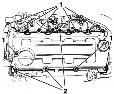
15. Remove camshafts. First of all, the exhaust camshaft is removed: moving in a spiral from the edges inward (in the sequence shown in Fig. illustrations), evenly loosen the bolts securing the upper shaft covers in several steps, then completely unscrew the bolts.
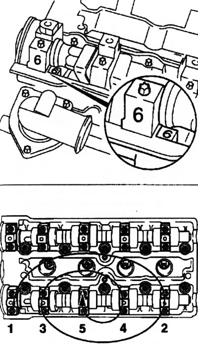
10.15. The sequence of releasing the fixing bolts of the upper covers of the camshaft support bearings - when removing the covers, pay attention to their numbering (Z14XE engine)
16. When removing the upper covers of the camshafts, pay special attention to their numbering (see illustration 10.6) - when assembling, the covers must be installed strictly in their original places. If for any reason the labels (numbers) are not available, they must be applied independently with a marker.
19. Raise the camshaft and remove it from the engine, carefully remove the oil seal.
20. Acting in a similar manner, remove the inlet camshaft - when installing the shafts must be installed only in their places.
21. Remove the valve lifters from the head and arrange them in the appropriate cups (see paragraph 6).
22. The procedure for checking timing components is given above (see paragraphs 7-9).
Installation
23. Lubricate the mating surfaces of the camshafts with fresh engine oil before installation. Clean the mating surfaces of the guides (front) bearings (see resist. illustration), apply fresh sealant (Green colour).
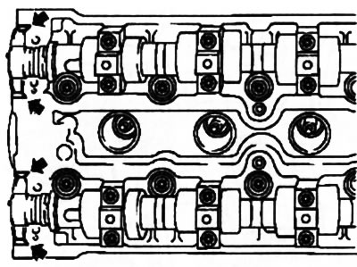
10.23. Places for applying sealant for the installation of thrust bearing caps (Z14XE engine) - indicated by arrows
Caution: Do not apply sealant too close to the oil passage holes (oil flows)! The installation of the covers must be completed no later than 10 minutes after the application of the sealant!
24. Install the intake valve shaft first and tighten the mounting bolts in the reverse order of release (see illustration 10.15), then install the exhaust valve shaft. After tightening the fasteners, remove excess sealant protruding from under the covers.
25. Press in new oil seals using the KM-422 tool (see resist. illustration) or other suitable tool. Before installation, lubricate the outer surfaces of the oil seals with silicone grease (white color).
10.25. Installing camshaft seals (the illustration shows an engine for another Opel model): 1. Adaptation KM-422; 2. A bolt of fastening of a gear pulley of a camshaft; 3. Washer
26. Before installing the cylinder head cover, clean all mating surfaces, replace the gaskets on the cover and apply fresh sealant (black color) (see resist. illustration). Establish a cover on a head of cylinders and tighten fixing bolts with the demanded effort.
10.26. Places (1) applying sealant when installing the cylinder head cover (Z14XE engine)
27. Install the camshaft gears (see Section 5). Adjust the valve timing and install the toothed belt (see Section 8).
28. Further installation is carried out in the reverse order of removal.
Z16SE engine
Removing
29. Unlike other gasoline engines on this engine, the camshaft thrust bearings are made on a separate timing case. If necessary, they can be replaced without changing the cylinder head.
30. Remove the toothed belt (see Section 8).
Note: If it is not necessary to replace the toothed belt, the right engine mount can be left in place. After loosening the tension, remove the belt only from the camshaft gear.
31. Remove the front section of the exhaust system, remove the remaining tract of the system from the holders, take it to the side and secure it with a wire in a suspended state (see chapter 4).
32. Release a nut of the lower bolt of fastening of the generator, holding a bolt the second key. Disconnect the wiring from the engine oil pressure switch and lower the vehicle.
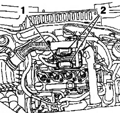
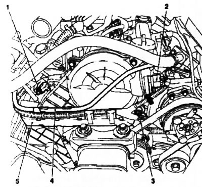
33. Disconnect all supply lines and electrical wiring from the throttle body assembly, remove 4 bolts (see resist. illustration) and remove the assembly from the engine.

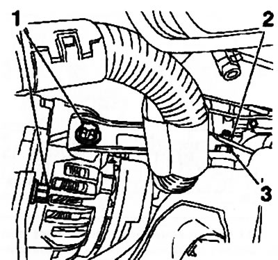
10.33. bolts (4) fasteners and supply lines of the throttle valve assembly (Z16SE engine): 1 EVAP vacuum hose; 2. Hoses of the cooling system; 3. PCV hose; 5. Wiring connector
34. Turn out and loosen the corresponding bolts of fastening of the generator (see resist. illustration) and move the generator back. Remove the generator mounting bracket.
10.34. Remove the bolts (1), loosen the bolts (2) And (3) and move the generator back (Z16SE engine)
35. Disconnect the electrical wiring from the following elements of the engine management system: EVAP valve, injectors, EGR valve, intake air pressure sensor, ECM module, ignition system DIS module, coolant temperature sensor, knock sensor.
36. Disconnect the vacuum lines of the brake booster, disconnect the supply line of the interior heater.
37. Relieve pressure in the fuel supply system (see chapter 4) and disconnect the fuel line (see resist. illustration).
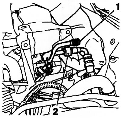
10.37. Disconnect the fuel line (2): 1. Service nipple protective cap
38. Disconnect the crankcase ventilation hose (PCV). Disconnect the BB wires and remove the ignition DIS module (see chapter 5).
39. Disconnect the lambda probe wiring connector, unscrew the 5 mounting bolts, remove the lifting eye and remove the exhaust manifold heat shield. Then release 8 nuts, remove the exhaust manifold and remove it from the engine compartment from below.
40. Disconnect the upper hose of the cooling system from the thermostat housing.
41. Turn out 5 fixing bolts and remove a cover of the case of a camshaft.
42. Remove the camshaft gear (see Section 5). Remove the 2 bolts and remove the rear timing cover.
43. Loosen the head mounting bolts in the reverse order of that shown in resist. illustrations. Carefully pry the housing under the camshaft installation with a suitable tool and remove it together with the shaft from the engine.

10.43. The procedure for tightening the cylinder head bolts (Z16SE engine)
44. Remove the tappets, hydraulic lifters, other valve drive elements and arrange them in the appropriate cups (see paragraph 6). Check the condition of the timing components (see paragraphs 7-9).
Installation
45. Before installation, lubricate the mating surfaces of the camshafts and hydraulic lifters, valve lifters with molybdenum grease (with MoS2 content).
46. Remove the remains of the old sealant and apply a layer of new (Green colour) on the mating surface of the cylinder head. Install the camshaft housing.
47. Further installation is carried out in the reverse order of removal. The order of a tightening of bolts of fastening of a head of cylinders is shown on an illustration 10.43.
Z13DT engine
Removing
48. Disconnect the wire from the negative terminal of the battery (see chapter 5), raise the vehicle on a lift, remove the multirib belt cover (see Section 5) and drain the coolant (see chapter 3).
49. Lower the car and remove the air cleaner (see chapter 4).
50. Disconnect the wiring connectors, disconnect the fuel lines and remove the fuel filter (see chapter 1).
Attention: Do not forget to close the free ends of the fuel lines with suitable plugs! On sale there are special sets of disposable plugs. If even small particles of dirt or sand enter the fuel system, serious engine damage can result!
51. Remove the expansion tank from the holders. Remove the fuel filter clamp (see chapter 4).
52. Disconnect the wiring connectors of 4 injectors, 4 glow plugs, camshaft sensor, crankshaft sensor, absolute pressure sensor in the intake manifold (MAP), EGR valve, fuel rail, camshaft pressure sensor, starter/generator harness. Turn out 3 bolts, separate a box of the cable channel of electroconducting from the engine and take it aside.
53. Loosen the 8 union nuts and remove the 4 injector high pressure fuel lines (see resist. illustration). Then loosen 2 more nuts and remove the fuel rail high pressure fuel supply line. Release the two return fuel lines from the clamps, disconnect the oil line, unscrew the 2 fixing bolts and remove the fuel distribution line.
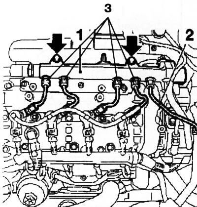
10.53. High pressure fuel lines (Z13DT engine) - the arrows indicate the bolts of the fuel distribution line (1): 2. Feed line; 3. Lines to nozzles
54. Remove 4 clips and separate the oil line from the nozzles.
55. Turn out 2 nuts, and take out nozzles from landing sockets together with fastening brackets (see resist. illustration).
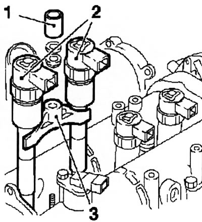
10.55. Removing nozzles (2) first and second cylinders (Z13DT engine): 1. Fixing nut; 3. Mounting bracket
Note: Each bracket holds 2 nozzles. The nozzles are removed in pairs: the first - second and third - fourth cylinders.
56. Remove the timing chain (see Section 8).
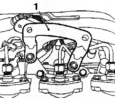
57. Turn out 2 bolts and remove the vacuum pump of the amplifier of brakes (see resist. illustration). Turn out 3 bolts and remove TNVD.
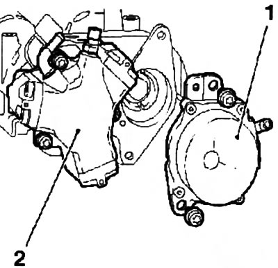
10.57. Vacuum pump (1) and injection pump (2) Z13DT engine
58. Loosen the bolts securing the camshafts and the shaft drive sprocket to the mounting housing, keeping the shafts from turning using the KM-956-1 and KM-6347 devices installed on the sprocket (see Section 5). Then completely unscrew the mounting bolt and remove the sprocket from the shaft.
59. Remove the 16 bolts around the perimeter of the camshaft mounting housing, and then the 2 central housing mounting bolts (see resist. illustration). Pry and carefully remove the housing from the motor head.
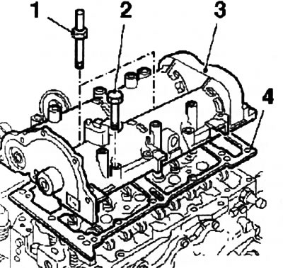
10.59. Frame (3) camshafts (Z13DT engine): 1. Set bolt; 2. Fixing bolt; 4. Gasket
60. Turn out a bolt and remove an inlet camshaft, remove a gear wheel a shaft. Then remove the exhaust camshaft in the same manner. Clean all removed components and their mating surfaces. Check the condition of timing parts (see paragraphs 7-9).
Installation
61. Lubricate the mating surfaces of the camshafts with fresh engine oil before installation. Install the shafts in the housing and secure them with bolts.
62. Set the shafts to the position corresponding to the TDC of the piston of the first cylinder, for which use the tools EN-46781 (see Section 6). Tighten the 3 shaft mounting bolts just enough to hold them in position (approx. 20 Nm).
63. Replace the gasket and install the housing on the cylinder head. Insert 2 set screws and center the body on the block heads. Align the side faces of the head of the block and the camshaft housing, use any suitable tool with a smooth edge to align them (see resist. illustration).
10.63. Chassis alignment (1) camshafts on the cylinder head using a tool (2) with a straight edge (Z13DT engine)
64. Tighten the housing mounting bolts with the required force (see specs) in the indicated on the sopr. sequence illustrations.
10.64. Tightening procedure for camshaft housing bolts (Z13DT engine)
Note: The long bolt must be installed in the position indicated by the number (14).
65. Further installation is carried out in the reverse order of removal. The camshaft bolts are fully tightened after installing the sprocket with force (120 Nm). When installing injectors, do not forget to replace the seals. Upon completion of work, fill the cooling and lubrication systems of the engine, if necessary, make the appropriate adjustments (see chapter 1). Check the tightness of the systems during the test drive.
Y17DT engine (L) /Z17DTH
66. Below is the shaft removal procedure for the Z17DTH engine. On Y17DT engines (L) the implementation of this procedure has some differences related to the layout of the power plant.
Removing
67. Disconnect the wire from the negative terminal of the battery (see chapter 5).
68. Remove the air cleaner (see chapter 4).
69. Disconnect the two electrical connectors from the engine control module (ECM) (see resist. illustration), remove the 2 bolts and 2 nuts and remove the module.
10.69. Connectors (2) ECM wiring harness (1) (Z17DTH engine)
70. Remove 4 mounting bolts and remove the ECM holder, and then remove 2 more bolts and remove the holder bracket (see resist. illustration).
10.70. bracket (1) ECM holder (Z17DTH engine)
71. Disconnect the injector wiring connectors (see resist. illustration) and glow plugs, release their wiring harness. Then, in turn, disconnect the wiring from the coolant temperature sensor, throttle assembly, air pressure sensor in the intake tract, camshaft sensor and solenoid valves.
10.71. Location of lines above the engine head Z17DTH: 1. Injector wiring connectors; 2. Intake air duct; 5. Return oil line; 6. Nozzles; 8. Nozzle sealing plates
72. Disconnect the intake air duct air cooler from the throttle valve assembly.
73. Remove 3 bolts, loosen the fastening clamp and remove the intake duct (see illustration 10.71).
74. Disconnect the crankcase ventilation hose (PCV) and remove together with the seal.
75. Remove the rear left rigging eye of the engine, then unscrew the 2 bolts and remove the guide tube of the dipstick for measuring the level of impellent oil.
76. Mark the installation position of both holders of the high pressure fuel lines and remove the holders (see resist. illustration).
10.76. Fuel lines (4) high pressure injectors for Z17DTH engine: 3. Holders; 7. Sealing plates for fuel supply lines of injectors
77. Prepare a container for draining fuel and disconnect the high-pressure fuel lines from the injectors - to loosen the union nuts, use special tools Hazet 4560-17 or Opel-KM-6098.
Attention: After removing the pipelines, to prevent contamination from entering the injection system, immediately close the openings of the line and nozzles with plugs!
78. Turn out a fixing bolt, weaken a collar and disconnect the returnable oil line of atomizers.
79. Separate the vacuum line, unscrew the fixing bolt and remove the cable channel (see resist. illustration).
10.79. cable channel (5) (Z17DTH engine) - the arrow indicates the camshaft sensor mounting bolt
80. Remove the toothed belt (see Section 8). Rotate the crankshaft 60°counterclockwise and remove the camshaft sprocket (see Section 5).
Note: The wheel is mounted on the intake camshaft and drives the exhaust camshaft through a gear train.
81. Remove the return oil line (see illustration 10.71) from injectors.
82. Remove the rear right engine lifting eye.
83. Turn out on 2 bolts and remove sealing plates of fuel lines of atomizers (see illustration 10.76).
84. Turn out on 2 bolts and remove sealing plates of nozzles (see illustration 10.71).
85. Disconnect the EGR cooler (EGR) from the camshaft housing cover.
86. Remove the mounting bolts (see resist. illustration), separate the camshaft housing cover and remove it together with the seal.
10.86. Mounting bolts (1) and hairpins (2) camshaft housing covers - the illustration shows the Y17DTL engine
87. Remove fuel injection nozzles (see chapter 4).
88. Block the exhaust camshaft together with the compensation gear from turning (see resist. illustration), for which remove the support bearing cover closest to the shaft gears and install the KM-6092-10 tool.
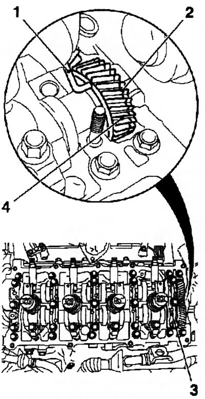
10.88. Exhaust camshaft gear lock (on the example of the Z17DTH engine): 1. Device KM-6092; 2. Compensation gear; 3. 5th camshaft bearing cap; 4. Gear of the exhaust camshaft
89. Moving in a spiral from the edges inward (in the sequence shown in Fig. illustrations), in several steps, 1-0.5 turns per approach, evenly loosen the bolts securing the upper shaft bearing caps, then completely unscrew the bolts. Before removing the covers, mark them so that they can be reinstalled in the same place later. Carefully remove the shafts - when removing the exhaust valve shaft, in addition to the KM-6092-10 tool, install the KM-6092 tool to securely fix the compensation gear on the camshaft gear (see resist. illustration).
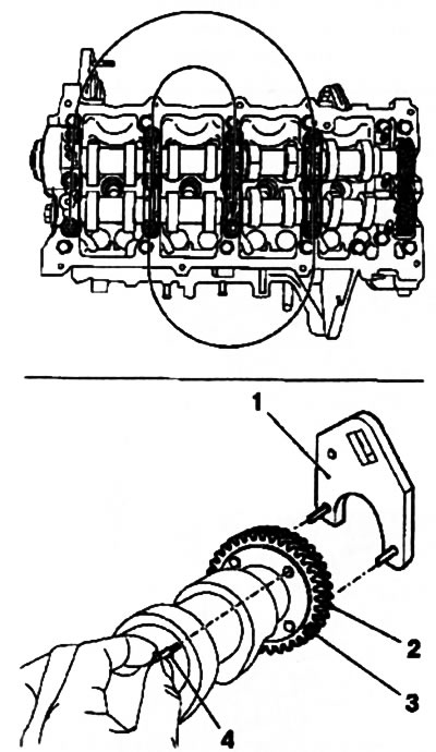
10.89. The procedure for releasing the camshaft bearing caps and fixing the compensation gear (2) on the gear (3) exhaust camshaft (Z17DTH engine): 1. Device KM-6092; 4. Device KM-6092-10
90. Carefully, so as not to damage the seating surfaces, remove the intake camshaft oil seal.
91. Check the condition of the timing components (see paragraphs 7-9).
Installation
92. If the exhaust shaft was replaced and the compensation gear was removed, to install it in the desired position, clamp the exhaust camshaft in a vise. Install the KM-6092 fixture in the appropriate holes (see illustration 10.89). By turning the compensation gear counterclockwise, align the holes of the gears and insert the KM-6092-10 tool.
93. Lubricate the mating surfaces of the shafts with clean engine oil. Before installing the shafts, engage their gears and install the shafts on the engine so that the exhaust shaft gear mark is between the intake shaft marks (see resist. illustration), while the marks should be approximately at the level of the upper edge of the camshaft housing. Apply sealant (Green colour) for sealing the joint of the first support bearing cover.
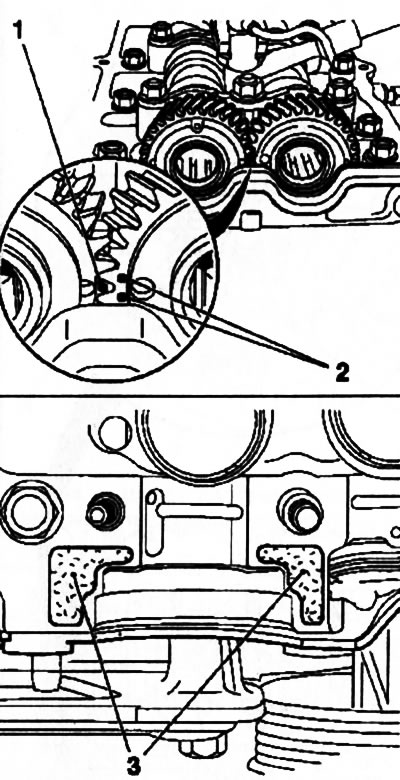
10.93. Alignment of camshaft gears (on the example of the Z17DTH engine): 1. Exhaust gear mark; 2. Intake shaft gear marks; 3. Places for applying sealant for the installation of the first cover of thrust bearings
94. Replace the four front covers and hand-tighten the bolts and nuts securing them.
Note: The arrows on the bearing caps must point towards the timing drive. Remove tool KM-6092-10 and install the fifth support bearing cover.
95. Tighten with the required force 10 fixing nuts and 5 bolts in several stages, making 1-1.5 turns per approach in the order of numbering shown on Ref. illustrations.
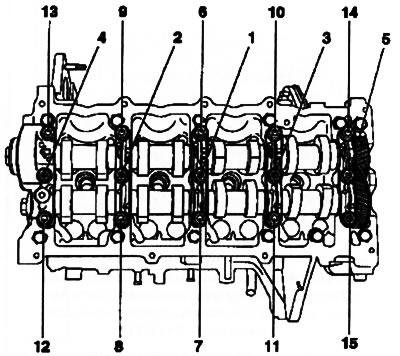
10.95. Tightening procedure for camshaft bearing caps (on the example of the Z17DTH engine)
96. Lubricate the outer surface of the new camshaft oil seal and install it using tool KM-656 (see resist. illustration).
10.96. Installing the stuffing box using the KM-656 tool (1) (on the example of the Z17DTH engine)
97. Install the camshaft gear (see Section 5), adjust the valve timing (see Section 6), install the toothed belt (see Section 8) and check and adjust the valve clearances (see Section 9). The rest of the removed components are installed in the reverse order of removal (see relevant sections and chapters).
Visitor comments