
Removing
1. The general connection diagram of the components of the intake tract of the air supply system is shown in resist. illustrations. Basically, the fastening of pipelines and sleeves is carried out by means of clamps of various types. In some cases, bolted connections are used for this purpose.
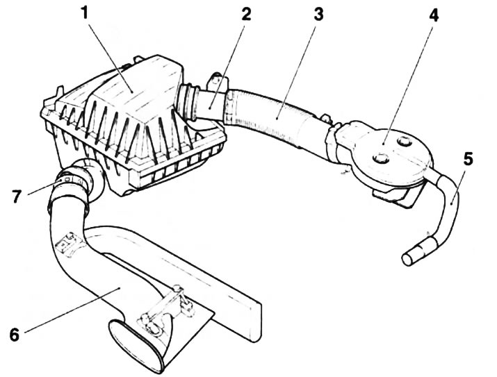
6.1a. intake air path (on the example of the Z12XE engine): 1. Air cleaner; 2. Air mass measurement sensor; 3. Intake air duct; 4. Inlet node; 5. Hose of the crankcase ventilation system; 6. Air intake of the air supply system with a resonator; 7. Connecting sleeve
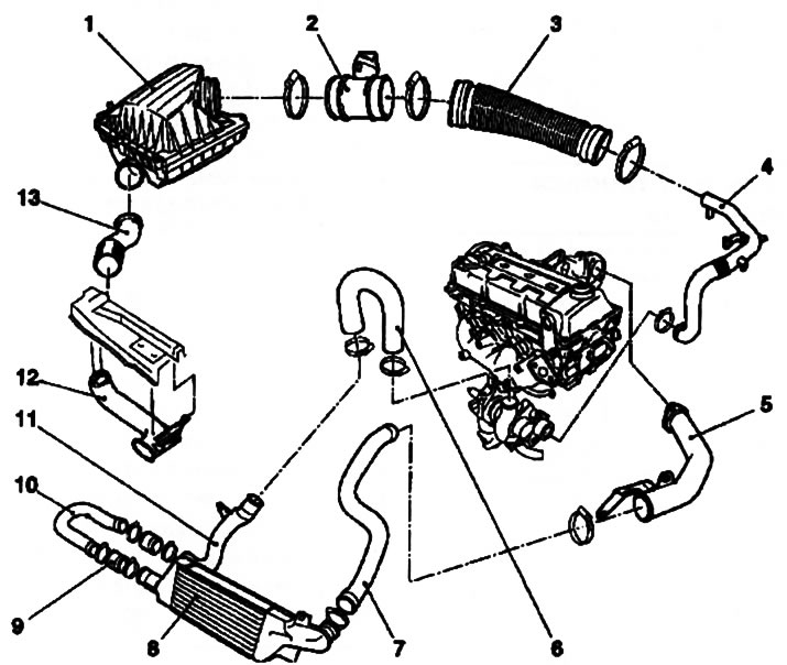
6.1b. Components of the intake air path of a turbocharged diesel engine (on the example of the Z17DT engine): 1. Air cleaner housing; 2. Air mass measurement sensor; 3. Intake air duct; 4. Inlet pipe; 5. Throttle body inlet; 6, 7, 9. Boost hoses; 8. Air cooler (intercooler); 10, 11. Boost pipes; 12. Air intake with resonator; 13. Connecting hose
2. The most important element of the air supply system is the air cleaner. When performing maintenance work, it is enough to remove only the top cover (see chapter 1), but when performing many repairs and replacing other elements of the engine compartment, it is necessary to dismantle the entire air cleaner assembly.
3. This Section describes in detail the procedure for removing the air cleaner on the Z13DT engine. On other engines, this operation is carried out similarly.
4. Pressing the latch in the direction indicated by the arrow (see resist. illustration), disconnect the air mass sensor harness connector. Release the wiring harness by cutting the holders, if necessary, mark their position for subsequent installation of new ones.
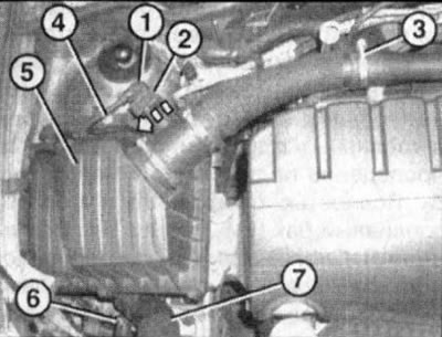
6.4. air cleaner (5) (on the example of the Z13DT engine): 1. Wiring connector for air mass measurement sensor; 2. Retainer; 3. Mounting collar; 4. Togh fixing screw; 6. Air cleaner support; 7. Connecting hose
5. With socket wrench (e.g. Hazet 426-7) loosen the clamp (see illustration 6.4) and disconnect the intake duct from the intake manifold.
6. Using a screwdriver (e.g. Hazet 837-T30), remove the TOX screw securing the air cleaner holder to the top of the suspension strut (see illustration 6.4)
7. Lift the air cleaner from the side of the holder and remove it from the support (see illustration 6.4) from the opposite side. Separate the connecting hose from the air cleaner and remove the cleaner assembly from the engine compartment.
Installation
8. Installation is done in the reverse order to the dismantling of the components. When installing the connecting hose, make sure that the protrusion on the air cleaner body nozzle matches the groove on the hose.
Note: The direction of the arrow on the air mass sensor must match the direction of the incoming air flow.
Visitor comments