
General information
1. Fuel is pumped into the system by an electric fuel pump installed together with a fuel reserve sensor in the body of the assembly, which is immersed in the fuel tank. On diesel engines Y17DT (L) Only the fuel gauge is installed in the tank. The fuel supply to the system is carried out at the expense of the injection pump.
2. The reserve sensor consists of a float and a potentiometer. When the fuel level drops, the sensor float drops, while the potentiometer connected to the float increases the electrical resistance of the sensor, and the corresponding signal is sent to the meter built into the instrument cluster (see chapter «Controls and methods of operation»).
3. When performing work, the fuel tank must not be filled with more than 2/3 of its capacity. Before removing the fuel pump assembly, empty the fuel tank to the required level by consuming fuel while the vehicle is moving, or by pumping fuel with a special pump through the tank filler neck. Work should be carried out in a well-ventilated, preferably equipped with a special hood, room.
Removing
4. Disconnect the negative cable from the battery (see chapter 5).
5. In order to gain access to the hatch in the floor panel, lift and remove the rear seat (see chapter 11). On Combo models (depending on configuration) tilt the rear seat, or unscrew the mounting bolts and remove the floor cover of the luggage compartment.
6. Fold back the carpet over the service hatch cover.
Note: The area of the carpet above the hatch has already been cut, but on newer vehicles there may be connecting bridges - carefully cut through with a sharp knife.
7. Pry and remove the service hatch cover (see resist. illustration) access to the fuel pump assembly.
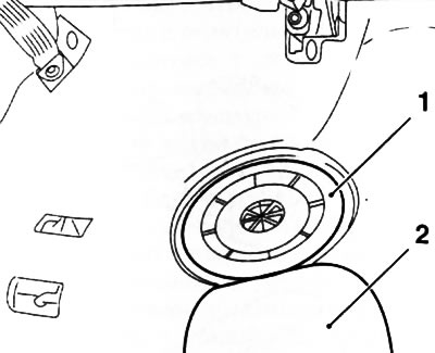
8.7. Service cover (1) manhole and valve (2) in carpet to access the fuel pump assembly
8. Disconnect the wiring connector (see resist. illustration) - fix the harness by gluing it with tape to the floor panel. Clearly mark, so as not to confuse during installation, the fuel lines of the supply and return lines, disconnect them from the fittings on the cover of the pump assembly. Plug the fuel lines immediately with suitable plugs to prevent fuel spillage and lay them aside. Remove traces of fuel leaks.
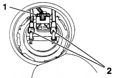
8.8. Connector (1) wiring and fuel lines (2) pump assembly
Note: When fuel lines are equipped with quick couplings, a special tool such as Hazet 4501-1 will be required to disconnect them.
9. Install special tool KM-797 (see resist. illustration) into the grooves of the retaining ring, unscrew and remove the ring. If no tool is available, place a plastic wedge or suitable wooden block in the groove of the retaining ring and unscrew the ring with light blows from a plastic or wooden hammer.
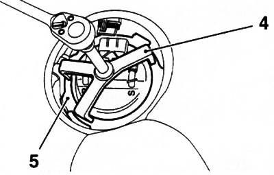
8.9. Special fixture KM-797 (4) to remove retaining ring (5) pump assembly covers
Attention: Never use metal objects for this - there is a risk of sparks during impacts!
10. Gently pull the cover up - it is connected to the body of the assembly by cable connectors and hose connections (see resist. illustration). After removing the cover, disconnect all supply lines and the sealing ring from its inside, if necessary, remember or write down the order of connecting the lines.
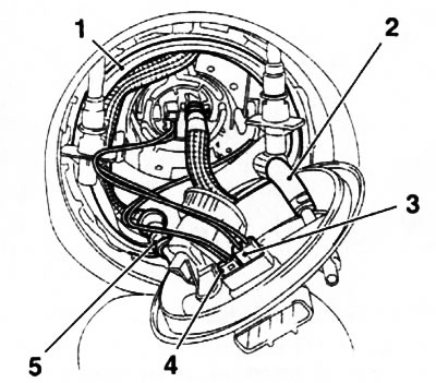
8.10. Laying electrical lines and hose connections of the cover of the electric fuel pump (on some models, the gasket pattern may differ slightly): 1. O-ring; 2. Fuel supply hose; 3. Connector for the electrical wiring of the fuel reserve sensor; 4. Wiring connector; 5. Fuel return hose
Note: On petrol models, a fuel tank pressure relief valve is built into the fuel pump cap. If necessary, the valve is replaced only complete with a cover.
11. Press the latch (see illustration 8.11a) in the direction indicated by the arrow (see illustration 8.11b) pull the sensor out of the assembly housing upwards.
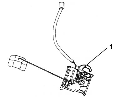
8.11a. Retainer (1) fuel gauge (sensor in the removed position) | 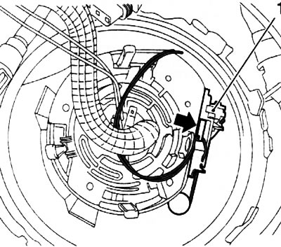
8.11b. Removing the sensor (1) fuel reserve |
12. Press 3 latches at the same time (see resist. illustration) assembly of the fuel pump and, holding them in this position, remove the pump from the fuel tank.
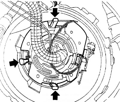
8.12. Fasteners (indicated by arrows) fuel pump assembly
13. Remove the pump from the housing and place it in a specially prepared container. Clean up any spilled fuel.
Installation
14. Install the pump in its original place, carefully fill the pump assembly housing into the tank and securely fasten it in the latches.
Note: If the pump is being replaced, change the wiring lines from the old one to the new one.
15. Further installation is carried out in the reverse order of removal. The sealing ring of the fuel pump assembly cover must be replaced without fail. After completing the work, check the system for leaks.
Note: The service cover and rear seat are installed after checking the tightness of the system.
Visitor comments