
Attention: Operations to remove the cylinder head should only be carried out when the engine is cold (ambient temperature) engine!
Note: Below is the procedure for removing the heads of engines equipped with the A/C system.
Z10XE engines (P) /Z12XE/Z14XEP
Removing
1. Disconnect the wire from the negative terminal of the battery (see chapter 5) and remove the air cleaner (see chapter 4), unscrew the mounting bolt on the upper front panel and remove the air intake.
2. On models equipped with Z12XE/Z14XEP engines, remove the front bumper trim (see chapter 11).
3. Drain the coolant (see chapter 3).
4. Hoses of the heating system from the throttle body, as well as the supply hose of the cooling system from the water pump.
5. Remove the brake booster vacuum line, disconnect the electrical wiring and disconnect the heater return hose.
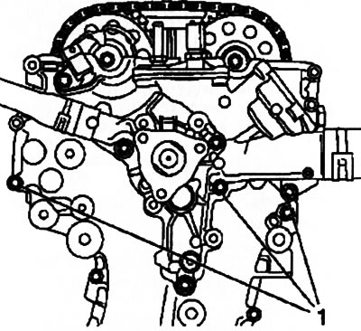
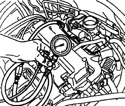
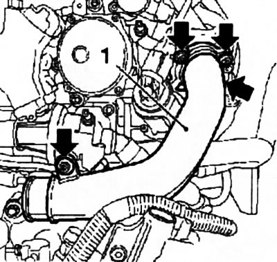
6. Relieve the pressure in the fuel system through the service fitting using a special device KM-J-34730-9 1 (see resist. illustration). Drain the fuel into a suitable container.
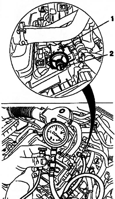
11.6. Installing the KM-J-34730-91 tool (2): 1. Service fitting; 2. Service port plug
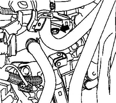
7. Using the KM-796 fixture (-A) disconnect the fuel line from the throttle body (see resist. illustration) and close the holes with suitable plugs.
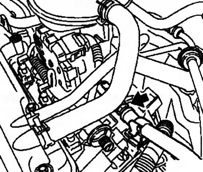
11.7 The arrow indicates the location of the fuel line disconnection from the throttle body (Z10XE engines (P) /Z12XE/Z14XEP)
8. Disconnect the fuel tank ventilation hose (EVAP) from the intake duct and move it aside.
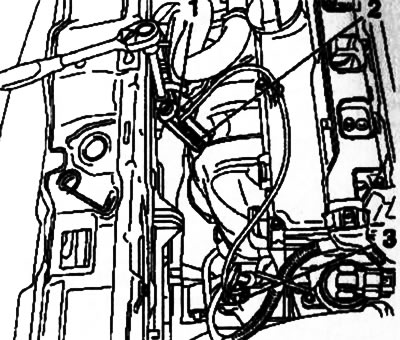
9. Disconnect the electrical wiring connectors shown in the resist. illustration and move the wiring harnesses to the side.
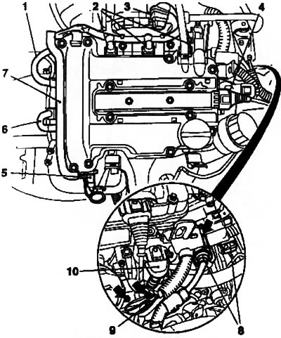
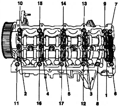
11.9. Connectors for electrical wiring of sensors and engine systems (on the example of the Z10XEP engine): 1. Camshaft sensor; 2. Injectors; 3. Throttle control systems; 4. Ignition module; 5. Engine oil pressure sensor; 6. Coolant temperature sensor; 8. Engine control module; 10. EGR valves. The arrows indicate the ground cable attachment points; 7. Cable channel; 9. Plug combination
Note: On Z10XEP and Z14XEP engines, the fuel rail cap must first be removed.
10. Remove the exhaust system (see chapter 4).
11. Disconnect the wiring from the starter, release the wiring harness from the holders on the intake duct.
12. Disconnect electroconducting from the K/V compressor, turn out 3 bolts and hang out the compressor.
Warning: The air conditioning system must not be opened! Observe the safety precautions given in the relevant section of Chapter 3!
13. Remove the tube of the dipstick for measuring the level of impellent oil. Disconnect the electrical wiring connector of the precatalytic lambda probe, then using the special tool KM-6129 (see resist. illustration), unscrew the probe.
11.13. Using the KM-6129 fixture (1) remove lambda probe (on the example of the Z10XE engine): 2. Left lifting eye
14. Turn out a bolt and remove the left lifting eye of the engine (see illustration 11.13), then remove the exhaust manifold heat shield bolts and remove it.
15. Remove 7 nuts (on Z12XE/Z14XEP engines - 9 nuts), remove the washers and remove the exhaust manifold.
16. Remove the oil filter cap (see chapter 1), and then unscrew the 3 bolts securing the filter housing (see resist. illustration) and remove it from the cylinder block.
11.16. bolts (2) case fastenings (1) oil filter (on the example of the Z10XE engine)
17. Remove the multirib belt (see Section 7).
18. Turn out 3 fixing bolts and remove a pulley of the water pump.
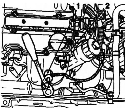
19. Turn out 3 bolts and disconnect a branch pipe of system of cooling from the water pump (see resist. illustration).
11.19. Cooling pipe on the water pump (on the example of the Z10XE engine)
20. Turn out bolts of fastening of the water pump and covers of a drive of GRM (see resist. illustration).
11.20. bolts (1) fixing the water pump housing - the arrows indicate the timing cover bolts (on the example of the Z10XE engine)
21. Remove the ignition module (see chapter 5).
22. Turn out 13 fixing bolts and remove a cover of a head of the block of cylinders.
23. Bring the piston of the first cylinder to the TDC position of the end of the compression stroke (see Section 6).
24. Remove the camshaft drive sprockets (see Section 8), carefully lower the chain into the timing case.
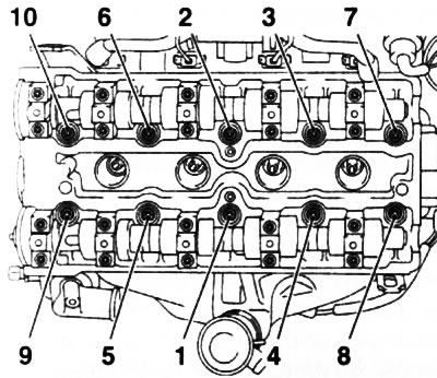
25. Loosen the head mounting bolts in the reverse order to that shown in Ref. illustrations, in 2 stages - in the first approach, loosen the bolts by 90°, and in the second - by 180°, then completely unscrew the bolts.
11.25a. The procedure for tightening the cylinder head of Z10XE engines (P) | 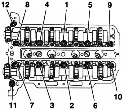
11.25b. The procedure for tightening the cylinder head of the Z12XE / Z14XEP engines |
26. Using the help of an assistant, remove the cylinder head - while the chain tensioner should move along its guide. The removed head should be laid on a wooden surface.
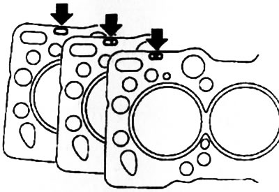
27. Remove the remnants of the sealant from the mating surfaces, carefully pry the gaskets at the points indicated on the resist. illustrations with arrows, and delete them.
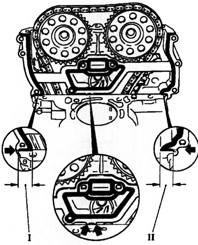
11.27. Seals on the inside of the timing cover
Installation
28. Install new gaskets and cut off protruding edges (I) from the timing case (see resist. illustration).
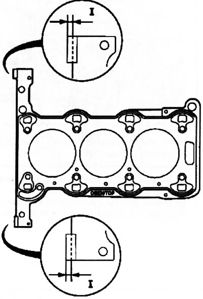
11.28. Installation of new gaskets sealing joints
29. Before installing a new head gasket, apply a bead of sealant (gray color) about 2 mm thick at the corners of the junction of the cylinder block with the timing case (see resist. illustration).
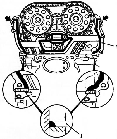
11.29. Installing new cylinder head gaskets: 1. Laying the vertical surface of the timing cover; 1. Places for applying sealant
Attention: Installation of the head must be completed no later than 10 minutes after applying the sealant!
Install a new head gasket marked «TOR» upwards and press in places where the sealant is to be applied. Insert the timing cover mounting bolts (see ibid), put the gaskets on the vertical surface of the timing cover and press the gaskets down at the places where the sealant is applied.
30. With the help of an assistant, install the block head - put the chain tensioner on the guide and, using the KM-955-1 tool, fix it.
31. Secure the block head by tightening the new head mounting bolts a few turns, tap the head using a rubber mallet towards the timing case and tighten the 3 drive cover mounting bolts (see resist. illustration).
11.31. Before tightening the block head mounting bolts, it is necessary to tighten the mounting bolts (1) timing cover
32. Tightening the cylinder head bolts is carried out in the sequence indicated in illustrations 11.25a and 11.25b, in 4 steps (see specs): in the first approach, tighten the bolts using a torque wrench, and in subsequent approaches, using a special protractor device.
33. Remove the previously installed 3 timing cover mounting bolts, install and tighten the removed water pump mounting bolts and then all the timing cover mounting bolts.
34. Installation of other components is made in an order, the return to an order of removal, thus replace all removed sealing linings. After installing the drive sprockets, adjust the valve timing (see Section 6).
Engines Z14XE/Z16XE/Z18XE
35. Disconnect the wire from the negative terminal of the battery (see chapter 5), if applicable, remove the engine cover (see section 2).
36. Drain the coolant (see chapter 3).
37. Remove the toothed belt (see Section 8), at the same time, if there is no need to replace the belt, the right engine support does not need to be removed. Turn out a fixing bolt and remove the directing roller of a gear belt from an inlet camshaft.
38. Disunite sockets of electroconducting of gauges of pressure and level of oil and the gauge of a cranked shaft.
39. Remove the exhaust system (see chapter 4).
40. Loosen the generator mount, for which unscrew the 2 upper bolts and separate the generator from the support, then loosen the fixing nut (see resist. illustration).
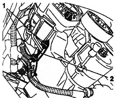
11.40. Top bolts (1) and nut (2) generator mounts (engines Z14XE/Z16XE/Z18XE)
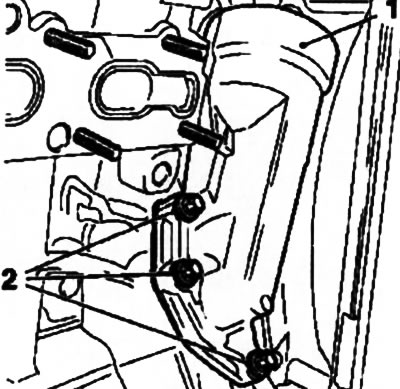
41. Remove the top bolt, loosen the bottom bolt and set aside the intake air duct bracket (see resist. illustration).
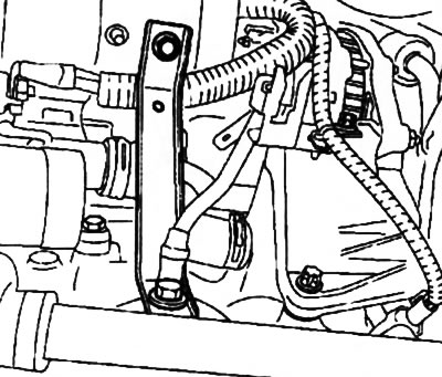
11.41. Air intake bracket (engines Z14XE/Z16XE/Z18XE)
42. Remove the ignition module (see chapter 5).
43. Disconnect the electrical wiring of the lambda probe, disconnect and take aside all the hoses on the cylinder head cover. Turn out 10 fixing bolts and remove a cover of a head.
44. Remove the camshaft gears (see Section 5) and remove the rear toothed belt cover.
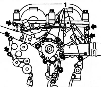
45. Disconnect the ground cable, unscrew the mounting bolts and remove the generator mounting bracket (see resist. illustration), then slide the generator back.
11.45. bolts (3,4,5) alternator mounting brackets (on the example of the Z18XE engine): 1. Earth cable; 2 Cable fixing nut
46. Release the pressure in the fuel system through the service fitting using a special tool KM-J-34730-91 (see resist. illustration). Disconnect the supply fuel line.
11.46. Installing the KM-J-34730-91 instrument (on the example of the Z18XE engine)
47. Disconnect the electrical wiring of the engine management system and the ground bus, take the wiring harnesses to the side.
48. Turn out 2 bolts and remove a fuel-distributing highway, remove an injector together with electroconducting.
49. Disconnect the power steering vacuum line and heater return hose. Disconnect the heater return hose from the throttle body.
50. Release 7 fixing nuts and remove the inlet pipeline/collector.
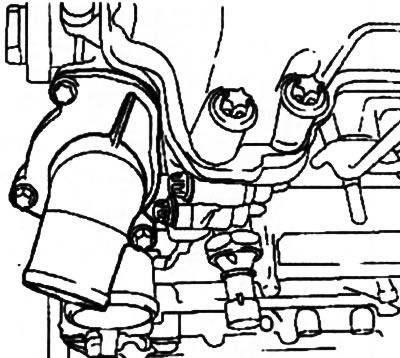
51. Turn out a fixing bolt (see resist. illustration) and disconnect the coolant hose. Disconnect the remaining hoses of the system that are attached to the engine head or impede access to it.
11.51. Bolt (indicated by an arrow) fastening of a branch pipe of the cooling system (on the example of the Z18XE engine)
52. Remove the mounting bolt and remove the air intake from the front panel.
53. Disconnect the electrical wiring connector of the pre-catalytic lambda probe, then using the special tool KM-6129 (see resist. illustration), unscrew the probe.
11.53. Removing the pre-catalytic lambda probe (2) using a special tool KM-6129 (1): 3. Wiring connector
54. Turn out 3 bolts and remove a heat-shielding screen of an exhaust manifold, if necessary, remove a tube of a probe of measurement of level of impellent oil. Loosen 9 nuts (on the Z18XE engine - 10 nuts) and remove the exhaust manifold.
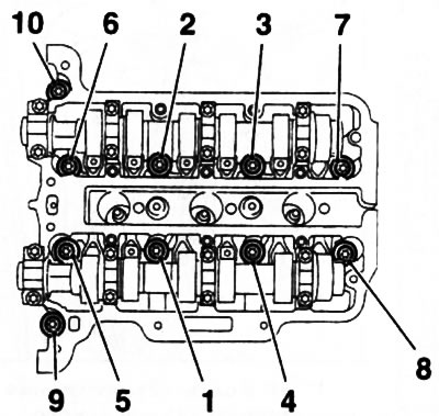
55. Loosen the head mounting bolts in the reverse order of that shown in resist. illustrations in two steps - at the first approach, loosen the bolts by 90°, and at the second - by 180°, then completely unscrew the bolts and remove the block head. Get help from an assistant if necessary.
11.55. Cylinder head tightening order (engines Z14XE/Z16XE/Z18XE)
56. Installation is carried out in the reverse order of removal, while replacing all sealing gaskets of the removed components. Tighten threaded connections to the required torque (see specs). When installing the block head, use new fixing bolts. The cylinder head bolts are tightened in the sequence shown in illustration 11.55 in 5 steps: at the first approach, tighten the bolts using a torque wrench, and at subsequent times with a special goniometric device.
Z16SE engine
57. The cylinder head is fastened with the same bolts as the camshaft housing - the operations for removing / installing the head are the same (see Section 10).
Z13DT engine
58. Remove the camshaft housing (see Section 10).
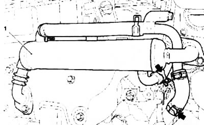
59. Disconnect the supply air pipe from the intake manifold (see resist. illustration).
11.59. bolts (indicated by arrows) air supply pipe fittings (1) (Z13DT engine)
60. Disconnect 3 hoses of the cooling system, thermostat housing and coolant temperature sensor.
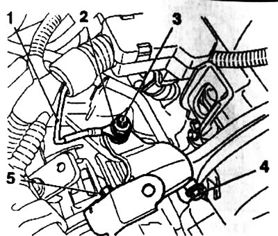
61. Separate the upper valve of the exhaust gas recirculation system (EGR) from fasteners (see resist. illustration). Turn out 2 bolts of fastening of the case of an oil separator and take away it from the engine.
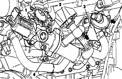
11.61. Upper EGR Valve Assembly Mount (Z13DT engine) - the arrows indicate the oil separator mounting bolts (3): 1, 4. Mounting bolts; 2. Retainer
62. Turn out a bolt of fastening of a branch pipe of system of cooling to a head of cylinders and take away a branch pipe. Loosen the bolt and remove the dipstick tube to measure the engine oil level.
63. Turn out bolts of fastening of a head in an order, the return shown on resist. illustrations. Use the help of an assistant and remove the head from the engine. The removed head should only be placed on a wooden surface.
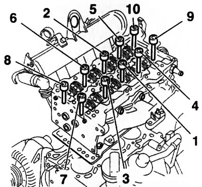
11.63. Cylinder head tightening order (Z13DT engine)
64. Before installing the head, it is necessary to fix the crankshaft flywheel from turning using a special tool (see Section 6).
65. For diesel engines, the thickness of the new cylinder head gasket is of particular importance. The measurement procedure is shown below (see «Y17DT engines (L) /Z17DTH»), and the size matching table is in the Specifications at the beginning of this chapter. Appropriate marks in the form of holes are applied to the gasket (see resist. illustration).
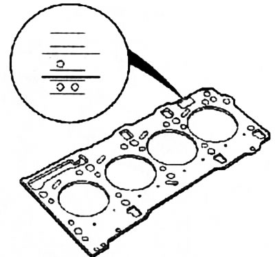
11.65. Cylinder head gasket marking for Z13DT engine
67. Tightening the cylinder head bolts is carried out in the sequence indicated in illustration 11.63 from 1 to 10, in 4 steps (see specs): on the first and second approaches, tighten the bolts using a torque wrench, and on subsequent approaches, using a special protractor device. New bolts must be used.
68. Further installation is carried out in the reverse order of removal.
Y17DT engines (L) /Z17DTH
Note: This subsection describes how to remove the Z17DTH engine head. Depending on the engine model and layout, some operations may differ from those shown below.
Removing
69. Operations on removal of a head of the block of the engine on the models equipped with the K/V system are described below. Before performing work, it is necessary to remove the refrigerant from the A/C system using special service equipment. It is recommended to entrust this operation to specialists - security measures are given in the appropriate section Chapters 3.
70. Disconnect the battery (see chapter 5) and drain the coolant (see chapter 3).
71. Remove the air cleaner (see chapter 4), multirib belt (see Section 7) and drain the engine oil from the crankcase (see chapter 1).
72. Do all the work given in Section 10, up to and including removal of the injectors.
73. Turn out 2 bolts of fastening of the heat exchanger of system EGR, lower 2 nuts, turn out a fixing bolt and remove the thermostat case, after having disconnected all hoses from it.
74. Disconnect the refrigeration line and electrical wiring from the compressor, separate the upper part of the dipstick tube for measuring the level of impellent oil.
75. Remove 2 fuses - 52, 53 (see chapter 12), remove the relay holder and disconnect the cooling module ground cable (EGR). Remove the top air duct.
76. Remove the front bumper cover (see chapter 11).
77. Disconnect the lower radiator hose, remove the lower branch pipe of the air discharge path.
78. Loosen the cooling module support bracket, use the help of an assistant and remove the module.
79. Turn out 3 fixing bolts and disconnect the forward end of an exhaust pipe from the forward catalyst. Disconnect the air hose from the turbocharger.
80. Turn out 3 bolts and remove the conditioner. Then unfasten and remove the air conditioner mounting bracket.
81. Loosen 2 fastening clamps (see resist. illustration), remove the 5 bolts and remove the EGR heat exchanger.
11.81. Clamps (indicated by arrows) fastening of the heat exchanger of the EGR system (Z17DTH engine)
82. After removing the 2 bolts, remove the dipstick tube for measuring the level of impellent oil from the top of the oil pan.
83. Remove 4 bolts and remove the exhaust manifold protection (see resist. illustration).
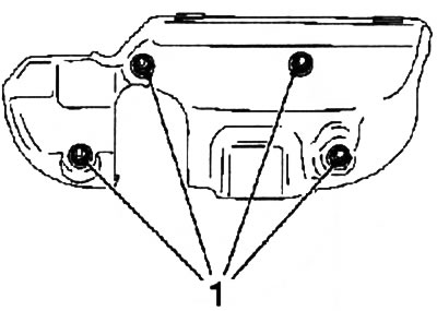
11.83. Mounting bolts (1) exhaust manifold protection (Z17DTH engine)
84. Disconnect the oil return line from the turbocharger, disconnect the turbocharger oil supply line from the engine block and then from the turbocharger housing.
85. Disconnect the vacuum line from the turbocharger control sensor. Turn out 2 bolts and 7 fastening nuts and remove an exhaust manifold together with a turbocharger (see resist. illustration).
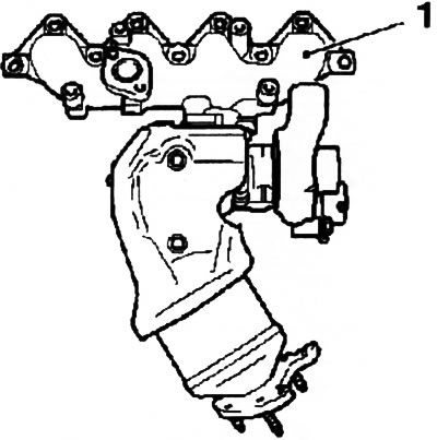
11.85. An exhaust manifold (1) with turbocharger housing (Z17DTH engine)
86. Separate the oil pump housing from the engine block, for which disconnect the hoses from it and unscrew the mounting bolt (see resist. illustration).
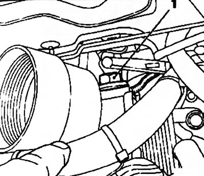
11.86. Mounting bolt (1) oil pump housing (Z17DTH engine)
87. Turn out 17 bolts of fastening of the case of camshafts in the specified order (see resist. illustration).
11.87. The order of releasing the bolts of the camshaft housing (Z17DTH engine)
88. Remove 16 cup pushers from the head - remember the order of their installation during assembly, they should be exactly in their places.
89. Turn out the fixing bolts of the cylinder head alternately in several stages, releasing them 1-0.5 turns per approach, in the order indicated on the resist. illustrations. Use the help of an assistant and remove the head.
11.89. The procedure for loosening the cylinder head bolts (Z17DTH engine)
Examination
90. After removing the head, it is necessary to clean the mating surfaces of the head and engine block and check them for surface deformation using a tool with a smooth straight edge (see resist. illustration).
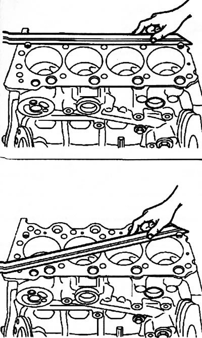
11.90. Checking the surface of the cylinder block for head installation
91. For diesel engines, the thickness of the new cylinder head gasket is of particular importance. To obtain the optimal volume of the combustion chamber, being at their TDC, the engine pistons protrude slightly above the surface of the block. To ensure that the piston and timing valves do not touch during operation, it is necessary to provide an appropriate clearance.
92. To measure the height of the protrusion of the piston above the surface of the block, it is necessary to install devices on the surface of the block (see resist. illustration) and expose «0» on the scale of the plunger-type meter at the moment when the meter probe is in contact with the surface of the block.
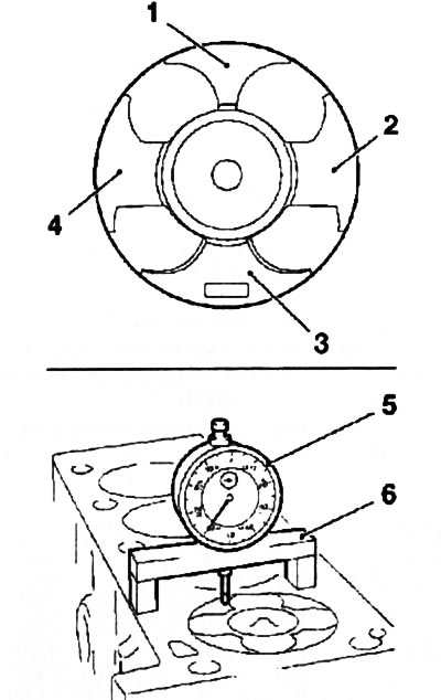
11.92. Piston protrusion measurement and measurement points (1,2,3,4): 5. Meter MKM-571-B; 6. Adaptation KM-301
93. Measure the height of the protrusion of all pistons one by one, making measurements at two points of each piston - for measurement it is necessary to select points (1) And (2) or another pair (3) And (4). When measuring, the crankshaft should be rotated smoothly to determine the highest lifting point of the pistons. At the end of the measurement Turn the crankshaft 60°counterclockwise.
94. Determine the thickness of the new gasket according to the data in the table (see specs). Gaskets are labeled accordingly (holes) (see resist. illustration).
11.94. Cylinder head gasket marking (Z17DT engines (L/H))
Installation
95. Installation is carried out in the reverse order of removal, while replacing all sealing gaskets of the removed components. Tighten threaded connections to the required torque (see specs). Cylinder head bolts are tightened in 3 or 5 steps (depending on the model): in the first approach, tighten the bolts using a torque wrench, and in subsequent approaches, using a special protractor device. When installing the head, use new mounting bolts. When tightening the cylinder head bolts, move in a spiral from the middle to the edges. Bolts of fastening of the case of camshafts are tightened in sequence, return shown on an illustration 11.89. Check valve adjustment (see Section 9).
Visitor comments