


Contents: Engines Z10XE(P)/Z12XE/Z14XEP ⬇ Features of Z14XE/Z16XE/Z18XE engines ⬇ Features of the Z16SE engine ⬇
1. A general description of the ignition system is given in Section 1. Detailed information about spark plugs, high-voltage wires and the procedure for replacing them is given in Section 22 Chapter 1. This section describes in detail the operations for removing and installing the ignition module.
Note: Disassembly and repair of the module in a regular repair shop is not performed - the module is replaced entirely. Ignition coils are not subject to repair.
Engines Z10XE(P)/Z12XE/Z14XEP
2. If equipped, remove the ignition module cover by sliding it in the direction indicated by the arrow (see accompanying illustration).
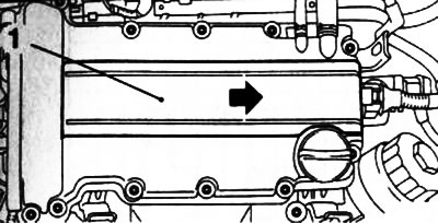
5.2. Ignition module cover (1)
3. Disconnect the electrical wiring from the ignition module and unscrew the 2 central bolts securing the module (see accompanying illustration).
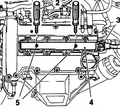
5.3. Removing the ignition module (4) (Z10XE(P)/Z12XE/Z14XEP engines): 2. Special handles KM-6009; 3. Electrical wiring connector; 5. Module mounting bolts
4. To remove the ignition module, use special handles that are screwed into the central threaded holes (see illustration 5.2). If they are not available, you can use a pair of long bolts of a suitable diameter with the appropriate thread pitch.
Note: These handles are also used to prevent burns to your hands when removing the ignition module on a hot engine.
5. When removing the ignition module, it is necessary to pull it straight up, try not to allow it to twist to avoid damaging the spark plug connectors.
6. Installation is carried out in reverse order.
Features of Z14XE/Z16XE/Z18XE engines
7. On these models you will need to remove the engine cover (see Chapter 2). The ignition module is secured with four bolts (on the Z18XE engine - five). Otherwise, the removal/installation procedure is completely similar to that described above for Z10XE(P)/Z12XE/Z14XEP engines.
Features of the Z16SE engine
8. On these models, the ignition module is mounted on the left side of the cylinder head.
9. To remove the module, disconnect the ignition module wiring harness connector and the 4 high-voltage wires.
10. Remove 3 bolts and remove the module from the cylinder head.
11. Installation is carried out in reverse order.
Visitor comments