
Note: The material below is descriptive only and is not tied to any particular make or model of vehicle. The rules for using the oscilloscope are described in detail in the instruction manual for its operation.
1. DMMs are great for testing electrical circuits that are in a static state, as well as capturing slow changes in monitored parameters. When conducting dynamic checks performed on a running engine, as well as identifying the causes of sporadic failures, an oscilloscope becomes an absolutely indispensable tool.
2. Modern oscilloscopes are usually equipped with only two signal wires, coupled with a set of various probes that allow you to connect the device to almost any device.
3. Some oscilloscopes allow you to save waveforms in the built-in memory module with subsequent printing of the results or transferring them to a personal computer carrier already in stationary conditions.
4. The oscilloscope allows you to observe periodic signals and measure voltage, frequency, width (duration) rectangular pulses, as well as the levels of slowly changing voltages. The oscilloscope can be used in the following procedures:
- a) Detection of unstable failures;
- b) Checking the results of the corrections made;
- c) Monitoring the activity of the lambda probe of the engine control system equipped with a catalytic converter;
- d) Analysis of the signals generated by the lambda probe, the deviation of the parameters of which from the norm is an unconditional evidence of a malfunction in the functioning of the control system as a whole. On the other hand, the correctness of the shape of the pulses emitted by the sensor can serve as a reliable guarantee of the absence of violations in the control system.
5. The reliability and ease of use of modern oscilloscopes do not require any special knowledge and experience from the operator. As a rule, the characteristics of the failed device are very different from the reference, which allows the operator to easily and quickly identify the failed component by analyzing the corresponding waveform. Interpretation of the received information can be made by an elementary visual comparison of the oscillograms taken during the test with time dependences typical for various sensors and actuators of automotive control systems.
6. The waveform produced by an oscilloscope depends on many different factors and can vary greatly. Therefore, before proceeding with the replacement of the suspect component in the event that the shape of the captured diagnostic signal does not match the reference waveform, you should carefully analyze the result.
7. Below is a description of some signal parameters and their brief characteristics.
8. Each signal taken with an oscilloscope can be described using the following basic parameters (see resist. illustration):
- a) Amplitude: The difference between the maximum and minimum voltages (IN) signal within the period;
- b) Period: Duration of signal cycle (ms);
- c) Frequency: Number of cycles per second (Hz);
- d) Width: Square wave width (ms, ms);
- e) Duty Cycle: Ratio of repetition period to width (In foreign terminology, the reverse duty cycle is used, a parameter called the duty cycle, expressed in%);
- f) Waveform: Square wave, burst, sine wave, sawtooth, etc.
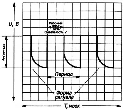
4.8. Characteristics of an arbitrary periodic signal
Voltage
9. The zero level of the reference signal cannot be considered as an absolute reference value, - «zero» real signal, depending on the specific parameters of the circuit under test, may be shifted relative to the reference [1] (see resist. illustration) within a certain acceptable range.
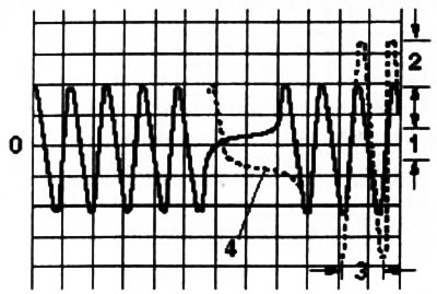
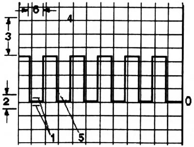
4.9. digital signal
10. The total amplitude of the signal depends on the supply voltage of the tested circuit and can also vary within certain limits relative to the reference value ([3] - see illustration 4.9 and [2] - see illustration 4.18).
11. In DC circuits, the signal voltage limits correspond to the supply voltage. An example is the idle speed stabilization circuit (IAC), the signal voltage of which does not change in any way with a change in engine speed.
12. In AC circuits, the signal amplitude already unambiguously depends on the frequency of the signal source, so the amplitude of the signal generated by the crankshaft position sensor (TFR) will increase with increasing engine speed.
13. In view of the above, if the amplitude of the signal taken with the oscilloscope is excessively low or high (up to cutting off the upper levels), you just need to switch the operating range of the device by switching to the appropriate measurement scale.
14. When checking the equipment of circuits with electromagnetic control (e.g. IAC system) voltage surges may occur when the power is turned off ([4] - see illustration 4.9), which can be safely ignored when analyzing the measurement results.
15. Also, don't worry about waveform distortions such as skew at the bottom of the leading edge of the square wave ([5] - see illustration 4.9), unless, of course, the very fact of the flattening of the front is not a sign of a malfunction in the functioning of the tested component.
Frequency
16. The frequency of repetition of signal pulses depends on the operating frequency of the signal source.
17. The shape of the recorded signal can be edited and brought to a form convenient for analysis by switching the scale of the time base of the image on the oscilloscope.
18. When observing signals in AC circuits, the time base of the oscilloscope depends on the frequency of the signal source [3] (see resist. illustration), determined by engine speed.
4.18. analog signal
19. As mentioned above, to bring the signal to a readable form, it is enough to switch the time base scale of the oscilloscope.
20. In some cases, the oscillogram of the signal turns out to be mirrored with respect to the reference dependence, which is explained by the reversibility of the polarity of the connection of the corresponding element and, in the absence of a ban on changing the connection polarity, can be ignored in the analysis.
Visitor comments