
Z10XE engines (P) /Z12XE/Z14XE (P)
Note: The alternator removal/installation procedure is described below using Corsa-C models as an example. On Meriva models, this work is done in a similar manner.
13. Disconnect the wire from the negative terminal of the battery (see Section 8).
14. Raise and place the front of the vehicle on stands. On Corsa-Eco models, remove the crankcase protection (see chapter 2).
15. Remove the multirib belt cover.
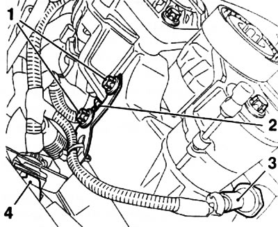
16. Loosen 2 fastening nuts and disconnect the supply wires from the generator (see resist. illustration).
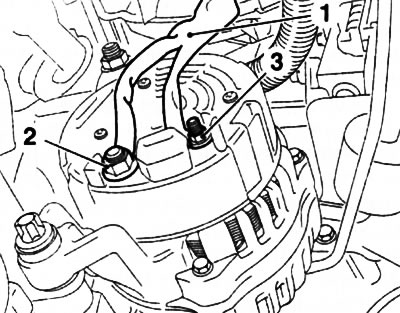
10.16. Nuts of fastening of the bringing electroconducting of the generator to the plug «B+» (2) and terminal «D+» (3): 1. Wiring harness
On models without air conditioning:
17. Loosen the tension of the multirib belt (see chapter 2) and remove the belt from the alternator drive pulley.
Note: When releasing the tensioner, it is necessary to fix its spring in a compressed position using the KM-955-2 tool (see resist. illustration).
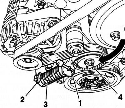
10.17. Depress the tensioner (3) for the central bolt (4) roller and fix it with a special tool KM-955-2 (Z10XE engines (P) /Z12XE/Z14XE (P) without K/V): 2. Lower tensioner mounting bolt
18. Remove the bottom bolt of the multirib belt tensioner (see chapter 2), disconnect the lambda probe connector and cut the wiring harness clamp.
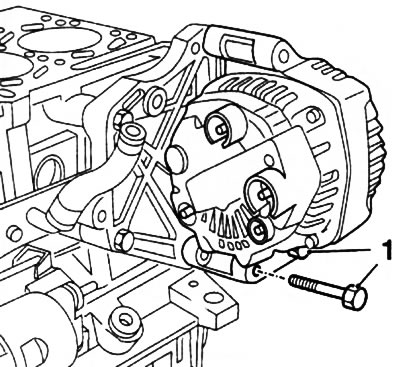
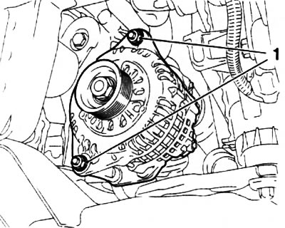
19. Loosen 2 nuts, remove 2 bolts (see resist. illustration), remove the alternator and carefully pull it down from the engine compartment.
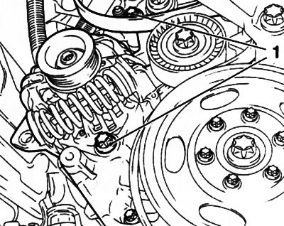
10.19. bolts (1) generator mounts (Z10XE engines (P) /Z12XE/Z14XE (P))
On models with air conditioning:
20. Loosen the tension of the multirib belt (see chapter 2) and remove the belt from the alternator drive pulley. Press the multirib belt tensioner again and remove the KM-6130 tool.
21. Turn out the top and bottom bolts of the tensioner and remove it.
Attention: After removal, the tensioner must be in a vertical position (the arrow printed on the device is pointing up), otherwise the damping fluid may leak out and the tensioner may fail!
22. Release 2 nuts of fastening of the generator and remove the holder of a socket of a lambda probe.
23. Remove 2 bolts (see illustration 10.19), remove the alternator and carefully pull it down from the engine compartment.
24. Installation is made in an order, the return to an order of removal.
Engines Z16XE/Z16SE/Z18XE (with air conditioning)
25. Disconnect the wire from the negative terminal of the battery (see Section 8), remove the multirib belt (see chapter 2).
26. Lower the car on wheels, remove the engine cover (see chapter 2) and air cleaner housing (see chapter 4).
27. On engines with a displacement of 1.6 liters, disconnect the coolant temperature sensor connector and separate the intake duct from the cylinder head. Then, disconnect the throttle assembly preheater return hose and crankcase breather hose.
28. Disconnect the holder of a plait of electroconducting and a hose from a basic arm of the generator.
29. On engines with a displacement of 1.6 liters, loosen the nut securing the generator support bracket.
30. On models with a Z18XE engine, loosen the nut and separate the ground cable (see resist. illustration).
10.30. Alternator Support Bracket: 1. Mass cable; 2. Fixing nut; 3. Hairpin; 4, 5. Fixing bolts
31. Turn out a hairpin and 2 bolts of fastening of a basic arm of the generator (see illustration 10.30), remove the bracket.
32. Raise and place the front of the car on stands.
33. On models with a Z18XE engine, depress the multirib belt tensioner, fix it with KM-6130. Turn out the central bolt of fastening and remove the tension device.
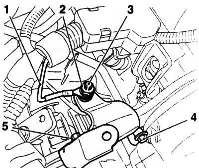
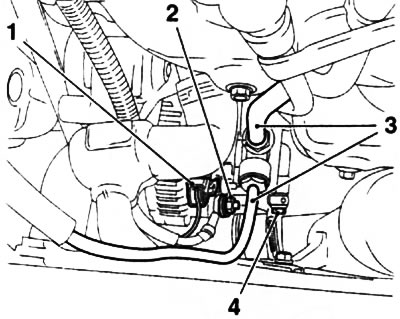
34. Disconnect the wiring connector (see resist. illustration) engine oil pressure sensor, remove the lambda probe.
10.34. Removing the generator (on the example of the Z18XE engine): 1. Top mounting bolts; 2. Fixing nut; 3. Engine oil pressure sensor connector; 4. Lambda probe
35. Separate from holders fuel and brake lines.
36. Turn out 2 top bolts of fastening of an arm of the generator and release a fixing nut (see illustration 10.34).
37. Turn out a bolt and remove an arm of the generator.
38. Pull out the generator mounting bolt, loosen the 2 fixing nuts and disconnect the generator supply wiring from the terminals «B+» And «D+».
39. Remove the generator from the engine compartment through the wheel arch.
40. Installation is made in an order, the return to removal.
Z13DT engine (with air conditioning)
41. Disconnect the wire from the negative terminal of the battery (see Section 8), and remove the air cleaner housing (see chapter 4).
42. Turn out the top bolt of fastening of the generator (see resist. illustration).
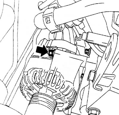
10.42. The arrow points to the upper alternator mounting bolt (Z13DT engine)
43. Raise and support the front of the car and remove the multirib belt (see chapter 2).
44. Loosen the 2 fixing nuts and disconnect the generator wiring from the terminals «B+» And «D+».
45. Turn out 2 bolts of fastening (see resist. illustration) and remove the generator.
10.45. bottom bolts (1) generator mounts (Z13DT engine)
Y17DT/Y17DTL engines
Note: On these models, the vacuum pump is mounted on the generator and is driven by the generator shaft.
Without air conditioner
46. Disconnect the wire from the negative terminal of the battery (see Section 8).
47. Disconnect the hoses from the vacuum pump (see resist. illustration).
10.47. Supply lines on the back of the generator (motors Y17DT/Y17DTL without K/V): 1. Terminal connector» 0+»; 2. Nut for fastening the wire to the terminal «B+»; 3. Vacuum pump hoses; 4. Hollow bolt
48. Place a container under the vacuum pump, unscrew the hollow bolt (see illustration 10.47) and separate the oil lines from the vacuum pump.
49. Separate the electrical wiring from the generator (see illustration 10.47).
50. Raise and place the front of the car on stands and remove the multirib belt (see chapter 2).
51. Separate the oil return hose from the vacuum pump, loosen the 2 nuts (see resist. illustration) and remove the generator. If necessary, remove the 3 bolts and remove the vacuum pump from the generator.
10.51. nuts (1) generator mounts (motors Y17DT/Y17DTL without K/V)
52. Installation is made in the reverse order of removal. If the vacuum pump was removed, replace its sealing gasket. Don't forget to replace the oil line o-rings.
With air conditioning
Note: On these models, to remove the generator, you will need to open the refrigerant circuit of the A/C system - contact a service station where there is equipment specially designed for this purpose and trained personnel.
53. Disconnect the wire from the negative terminal of the battery (see Section 8).
54. Remove the refrigerant from the A/C system - contact a specialist.
55. Remove the air cleaner housing (see chapter 4).
56. Release the brake booster vacuum hose from the five holders and take it aside.
57.. Loosen 2 clamps and remove the boost hose, and then remove the central boost pipe.
58. Remove the front bumper cover (see chapter 11).
59. Loosen the fastening clamp and disconnect the lower boost pipe from the intercooler.
60. Disconnect the line of the A/C system and take it aside.
61. Further removal is carried out as on models without air conditioning.
62. Installation is carried out in the reverse order of removal.
Engine Z17DTH (with air conditioning)
Note: On these models, to remove the generator, you will need to open the refrigerant circuit of the A/C system - contact a service station where there is equipment specially designed for this purpose and trained personnel.
Note: On these models, the vacuum pump is mounted on the generator and is driven by the generator shaft.
63. Disconnect the wire from the negative terminal of the battery (see Section 8).
64. Remove the refrigerant from the A/C system - contact a specialist.
65. Raise and support the front of the car and remove the multirib belt (see chapter 2).
66. Place a container under the vacuum pump, unscrew the hollow bolt (see resist. illustration) and separate the oil lines from the vacuum pump.
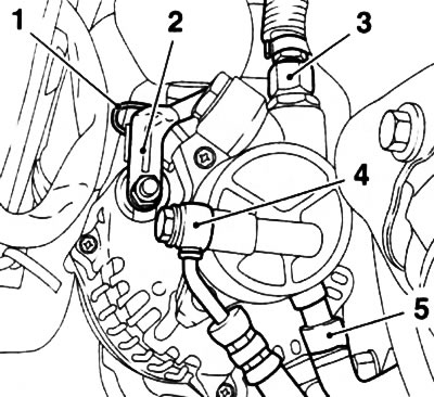
10.66. The vacuum pump is mounted on the back of the generator (Z17DTH engines): 1. Wire to terminal» 0+»; 2. Wire to terminal «B+»; 3. Vacuum hose of the brake booster; 4. Hollow bolt; 5. Oil drain hose
67. Disconnect the oil level sensor connector. Disconnect the brake booster vacuum hose from the vacuum pump (see illustration 10.66)
68. Separate the electrical wiring from the generator (see illustration 10.66).
69. Turn out the top bolt of fastening of the generator, release the bottom nut, take the generator from the holder and take a bolt.
70. Turn out a fixing bolt and disconnect the line of the K/V system. Remove the generator from the engine compartment.
71. Installation is carried out in the reverse order of removal. Be sure to replace any gaskets that were removed.
Visitor comments