
General information
1. The vehicles in question use an alternator. When installing additional electrical equipment, check that the generator has enough power to provide electricity to new consumers.
2. The generator is driven by a multirib belt from the engine crankshaft.
3. The generator is an electrical machine with electromagnetic excitation. A rectifier is built into the generator to convert AC to DC. The output voltage is regulated by a built-in regulator.
4. When the generator is running, the electric current flowing through the field winding creates a magnetic flux around the rotor poles. When the rotor rotates, its magnetic poles periodically change under each stator tooth, as a result, the magnetic flux passing through the teeth continuously changes in magnitude and voltage. This variable magnetic flux creates an electromotive force in the stator winding (EMF).
5. At a high rotor speed, when the generator output voltage begins to exceed 13.6-14.5 V, the voltage regulator is locked, and no current passes through the field winding. When the voltage drops, the regulator opens again, allowing free flow of current through the field winding. The higher the rotor speed, the longer the regulator remains locked and, accordingly, the voltage at the generator output decreases more. The process of locking and unlocking the regulator occurs at a high frequency, so the output fluctuations remain almost imperceptible and the generator voltage can be considered constant, maintained at the level of 13.6-14.5 V.
6. The charging system does not require periodic maintenance, however, the condition and replacement of the alternator drive belt, battery and its wiring should be done on a regular basis in accordance with the maintenance schedule (see chapter 1).
7. The serviceability of the charge system is monitored using the corresponding lamp on the instrument cluster.
Generator Maintenance Safety Precautions
- Do not disconnect the battery or voltage regulator while the engine is running;
- Do not ground the generator excitation terminal or the cable attached to it;
- Do not confuse the order of connecting the voltage regulator wiring;
- When charging the battery without removing it from the car, make sure that both wires are disconnected from it;
- Remember that the inclusion of a voltage regulator closed to ground leads to its instantaneous failure;
- Never remove the generator with the battery connected;
- Never use voltage meters or test lamps connected to a household network when checking on-board electrical equipment (110/220V);
- When checking the condition of the diodes, do not apply a voltage of more than 12 V to them and do not use megohmmeters, which also have a high output voltage - breakdown of the diodes will lead to a short circuit. Remember that when checking the insulation of the electrical wiring with a megohmmeter, it is necessary to disconnect all electrical wiring from the generator;
- Before carrying out any electric welding work on the car, do not forget to disconnect the electrical wiring from the generator and battery;
- Any checks of circuits and on-board wiring assemblies should be carried out with the engine off and the battery disconnected;
- Remember that reversing the polarity of any connections carries the risk of permanent damage to the rectifier and generator voltage regulator.
Alternator voltage test
8. If the battery does not charge or is not sufficiently charged while the car is moving, check the voltage of the generator.
9. Connect a voltmeter between the positive and negative battery terminals and start the engine. The voltage at start should drop to about 8V (at ambient temperature +20°С)
10. Increase the engine speed to 3000 rpm - if the generator and regulator work properly, the voltage at the terminals should be from 13 to 14.5 V
11. To check the stability of the voltage, turn on the high beam and repeat the measurements at 3000 / min. Measured voltage - should increase by more than 0.4 V from previously measured values.
12. If the indicators are outside the nominal value, the generator and regulator must be checked in a specialized workshop.
Removal and installation
Engine Z16XE/Z18XE
13. Disconnect a wire from the negative plug of the storage battery. (see Section 8), remove the multirib belt and the belt tensioner (see chapter 2).
14. Disconnect the wiring connector (see resist. illustration) engine oil pressure sensor, loosen the fixing nut, unscrew the 2 upper bolts of the alternator bracket and loosen the lower bolt.
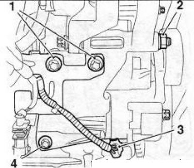
10.14 Removing the generator (Z18XE engine): 1. Top mounting bolts; 2. Fixing nut; 3. Engine oil pressure sensor connector; 4. Lower mounting bolt
15. Lower the car on wheels remove the engine cover.
16. Remove the EVAP valve.
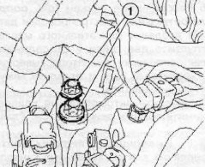
17. Loosen 2 fixing nuts (see resist. illustration) and disconnect the supply wiring from the generator.
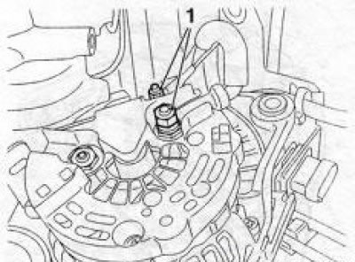
10.17 Nuts (1) generator wiring harness (Z18XE engine)
18. On models equipped with the Z16XE engine, unscrew the 2 upper, and on models with the Z18XE engine - 1 upper and 1 lower mounting bolts, remove the generator together with the mounting bracket and remove them from the engine compartment. If necessary, remove the bolts and remove the bracket from the generator.
19. Installation is made in an order of the return to removal. In this case, the sleeve of the tensioner of the multi-ribbed belt must coincide with the hole on the generator support.
Engines Z22SE/Z22YH
20. Disconnect a wire from the negative plug of the storage battery.
21. Remove the multirib belt.
Note: The belt is removed from below.
22. Release a nut and take an axial bolt of a forward support of the engine.
23. Lower the car on wheels, fill in coolant and remove the engine cover.
24. Remove the air cleaner, and disconnect the upper hose of the cooling system from the cylinder head.
25. Remove the EVAP valve (see chapter 4).
26. Remove the right engine mount using a lifting device and raise the engine approximately 3.5 cm.
27. Disconnect the connector (see resist. illustration) and loosen the alternator wiring nut. Turn out 4 fixing bolts, remove and take the generator from an impellent compartment.
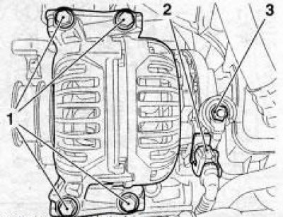
10.27 Bolts (1) generator mounts (engines Z22SE/Z22YH): 2. Wiring connector; 3. Wiring nut
28. Installation is carried out in the reverse order.
Z32SE engine
29. Disconnect a wire from the negative plug of the storage battery.
30. Remove the multirib belt.
31. Remove the intermediate drive shaft and disconnect the right stabilizer link from the shock absorber.
32. Loosen the starter screen, loosen the 2 nuts securing the generator wiring and disconnect the wires.
33. Turn out 2 bolts and take the generator from an impellent compartment from below.
34. Installation is carried out in the reverse order.
Z19DT engine (H)
35. Disconnect the wire from the negative battery terminal (see chapter 5) and remove the engine cover (see chapter 2).
36. Remove the fuel filter housing from the mounting clamp and remove the last (see Chapter 4, Section 10).
Note: For convenience, the fuel filter can be removed completely.
37. Raise the car on a lift and remove the multirib belt (see chapter 2).
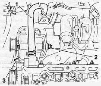
38. Remove the bolt (see resist. illustration) mount the generator and lower the vehicle.
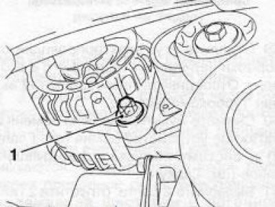
10.38 Fixing bolt (1) generator (Z19DT engines (H))
39. On the Z19DTH engine, unscrew the 2 bolts securing the upper holder of the generator wiring harness and separate the harness.
40. Release 2 nuts and disconnect generator wiring.
41. Turn out 2 (on the Z19DT engine one) upper mounting bolts, remove and remove the generator from the engine compartment upwards.
10.41 Top bolts (1) generator mounts (Z19DTH engine)
42. Installation is carried out in the reverse order.
Y20DTH/Y22DTR engines
43. Disconnect the wire from the negative terminal of the battery (see Section 8), and remove the multirib belt (see chapter 2).
44. Remove the exhaust system (see chapter 4).
45. Turn out 2 bolts, weaken 1 nut and remove the screen of a starter.
46. Disconnect the connector (see resist. illustration) the electrical wiring of the engine oil pressure sensor, loosen the two nuts and disconnect the electrical wiring of the generator, unscrew the mounting bolt and separate the casing of the cable channels.
10.46 Bottom bolt securing cable duct cover (2) (motors Y20DTH/Y22DTR): 1. Engine oil pressure sensor
47. Lower the car on wheels, remove the engine cover.
48. Turn out 2 top bolts of fastening of a casing of cable channels of the generator.
49. Remove an inlet air path.
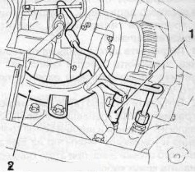
50. Release the hose (see resist. illustration) cooling system from the upper holder, loosen the alternator fastening nut and remove the hose holder.
10.50 Upper (2) and lower (3) alternator mounting nuts: 1. coolant hose
51. Raise the car on a lift, remove the 3 mounting bolts and remove the steering heat shield.
52. Loosen the bottom nut (see illustration 10.50) generator mounts. Remove the upper and lower mounting bolts and remove the generator from the engine compartment down, while holding the casing of the cable channels.
53. Installation is carried out in the reverse order.
Y30DT engine
54. Remove the dipstick for measuring the level of impellent oil and close the tube with a suitable plug.
55. Turn out 4 screws and remove a cover of the engine.
56. Remove the battery from the installation tray.
57. Loosen the mounting clamp, disconnect from the turbocharger and set aside the lower connecting one.
58. Remove a broad tank, release a nut and release a hose of a broad tank from the holder. Loosen the holder.
59. Separate the wiring harness from the gearbox and take it aside. Disconnect the turbocharger heat shield.
60. Remove multirib belt and belt tensioner (see chapter 2) and exhaust system (see chapter 4).
61. Remove the 2 bolts, loosen the 2 nuts and remove the catalytic converter support bracket, then loosen the 2 nuts and remove its heat shield.
62. Remove the multirib belt guide roller (see chapter 2).
63. Remove the right drive shaft (see chapter 8).
64. Release 2 nuts and disconnect an electroconducting from the generator. Release the electrical wiring from the holder, unscrew the bolt and remove the holder.
65. Disconnect the casing of the generator cable channels and the starter wiring and take them aside.
66. Turn out 2 bolts of fastening of the generator, turn it by a pulley towards a case of the steering mechanism and take the generator from an impellent compartment.
67. Installation is performed in the reverse order of removal. Upon completion of installation, check the coolant level and make appropriate adjustments if necessary.
Visitor comments