
General information
1. The sole purpose of the starting system is to ensure that the engine is spinning at a speed sufficient to start it - approximately 300 rpm.
2. The starting system consists of a starter, battery, ignition switch, traction relay and connecting wiring.
3. Depending on the model, different brands of starters may be installed. Below is the general principle of the starter.
4. The starter is a mixed-excitation DC electric motor with an externally mounted electromagnetic traction relay. The starter consists of a housing or a stator with excitation windings, an armature with an overrunning clutch, a cover with brush holders and a traction relay.
5. When the starter is turned on, current from the battery begins to flow through the winding of the traction relay. The relay armature is pulled in and the contacts are closed. At the same time, the relay armature through the drive lever ensures the extension of the gear with the overrunning clutch, while the clutch hub rotates on the screw splines of the starter armature shaft and also turns the gear, which facilitates the engagement of the latter with the flywheel ring gear. A current passes through the closed contacts of the traction relay, which feeds the stator and armature windings, and the starter armature begins to rotate together with the hub and freewheel.
6. After starting the engine, the speed of the gear exceeds the speed of the starter armature. In this case, the overrunning clutch turns freely, and torque is not transmitted from the engine flywheel to the starter armature shaft. After releasing the ignition key, the power circuit of the windings of the traction relay opens through the ignition switch, the armature of the traction relay is pressed back to its original position by a spring, the relay contacts open and the drive gear disengages from the flywheel ring gear.
7. A starter with a retractor is located parallel to the engine crankshaft and mounted on the power unit.
8. When carrying out maintenance, it is necessary to ensure an impeccable connection of the electrical wiring, remove traces of corrosion on the clamp and lubricate the terminals with special grease.
Removal and installation of a starter
Engines Z16XE/Z18XE
9. Disconnect the wire from the negative terminal of the battery (see Section 8) and raise the car on a lift.
10. Disconnect the connector (see resist. illustration) electrical wiring of the lambda probe, remove the 2 bolts and remove the support bracket for the exhaust pipe of the exhaust system.
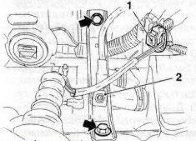
12.10 Bolts (indicated by arrows) support bracket fasteners (engines Z16XE/Z18XE): 1. Lambda probe wiring connector; 2. Cable «masses»
11. Loosen 2 fixing nuts (see resist. illustration) and disconnect the lead wire from the starter, as well as the ground cable.
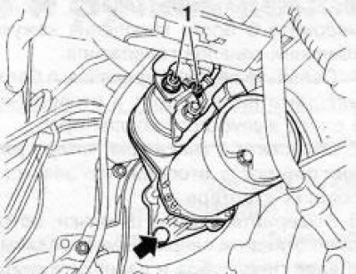
12.11 Nuts (1) starter wiring harness (engines Z16XE/ Z18XE) - the arrow indicates the lower starter mounting bolt (the second one is not visible in the picture)
12. Turn out 2 fixing bolts (see illustration 12.11) and remove the starter.
13. Installation is carried out in the reverse order.
Z32SE engine
14. Remove the generator (see Section 10).
15. Release 2 fixing nuts and disconnect an electroconducting of a starter.
16. Turn out 2 bolts and take a starter from an impellent compartment downwards.
17. Installation is carried out in the reverse order.
Z19DT engines (H)
18. Disconnect the wire from the negative terminal of the battery (see Section 8).
19. Remove the engine cover (see chapter 2), raise the car on a lift and remove the crankcase protection (see Chapter 2, Section 5).
20. Loosen 3 nuts (see resist. illustration) and disconnect the wiring harness from the starter. Loosen the 2 nuts and disconnect the harness holder, move the harness to the side.
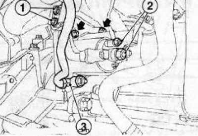
12.20 Starter mounting (Z19DT engines (H)) - the arrows show the upper mounting bolts: 1. Nuts for fastening the holder of the wiring harness; 2. Nuts for fastening electrical cables; 3. Nut for fastening the ground cable; 4. coolant hose
21. On the Z19DTH engine, remove the starter studs.
22. Lower the car on wheels, disconnect a broad tank and take it aside.
23. On the Z19DTH engine, disconnect the 2 cooling system hoses and disconnect the starter and alternator wiring harness.
24. Turn out 2 top fixing bolts (see illustration 12.20), separate the wiring harness and remove the starter from the engine compartment upwards.
25. Installation is carried out in the reverse order.
Y20DTH/Y22DTR engines
26. Disconnect the wire from the negative terminal of the battery (see Section 8).
27. Turn out the top bolt of fastening of a starter and raise the car on the elevator.
28. Remove the crankcase protection (see Chapter 2, Section 5) and exhaust system (see chapter 4).
29. Turn out 2 bolts, weaken a fixing nut and remove the screen of a starter.
30. Disconnect the connector (see illustration 10.46) wiring of the engine oil pressure sensor, unscrew the 3 bolts securing the casing of the cable channels of the generator.
31. Loosen the upper mounting bolt, remove the lower bolt and disconnect the exhaust manifold support.
32. Loosen 3 nuts (see resist. illustration) and disconnect the starter wiring.
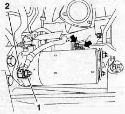
12.32 Starter wiring nuts
33. Unscrew the lower studs, carefully lift the casing of the generator cable channels up and remove the starter from the engine compartment down.
34. Installation is carried out in the reverse order.
Y30DT engine
35. The procedure for removing the starter is almost the same as the procedure for removing the alternator described in Section 10, with the following exceptions: you do not need to remove the multi-ribbed belt, but you will need to remove the front suspension subframe (see chapter 10).
Check of the traction relay of a starter
36. The most common cause of a malfunction of the starter is the failure of the traction relay. As a result, the gear does not engage with the flywheel ring gear and the starter does not crank the engine. Checking the traction relay can be carried out both on the engine and after removing the starter. Either test method requires a fully charged battery.
Check on the engine
37. Turn off the ignition, set the selector lever to the position «R» / shift into neutral.
38. Raise the car on a lift and place it on stands. On diesel models, remove the protectioncrankcase.
39. Connect the auxiliary cable/wire to the terminal «50» traction relay (a thin wire is attached to the terminal, laid from the ignition switch
40. Short the other end of the auxiliary cable/wire to the terminal «30» (a thick cable laid from the battery is fixed to the terminal).
41. When the terminals are closed, the gear of the traction relay should move forward. If this does not happen, close the traction relay.
Check after removing the starter
42. Remove the starter (see above).
43. Connect the starter housing with an auxiliary cable/wire to the negative pole of the battery.
44. Connect the second auxiliary cable / wire with one end to the positive pole of the battery, shortly short the other end to the terminal «50» traction relay.
45. When the terminals are closed, the gear of the traction relay should move forward. If this does not happen, replace the traction relay.
Check of a condition and recovery repair of a starter
46. Performing a detailed diagnosis of the condition and restoring the starter should be entrusted to car service specialists - first make sure that the cost of the repair does not exceed the price of a new starter.
Visitor comments