
2. Scratch a line through the stator housing and front end cover to ensure proper installation later.
3. Unscrew and remove the three through bolts, and then remove the front rotor cover from the rear end housing and stator. Check the condition of the removable rings; they may need cleaning with a cloth soaked in gasoline or very gentle sandpaper (see photo 10.3 A and B).
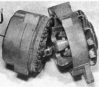
Photo 10.3A Generator with drive end bracket removed
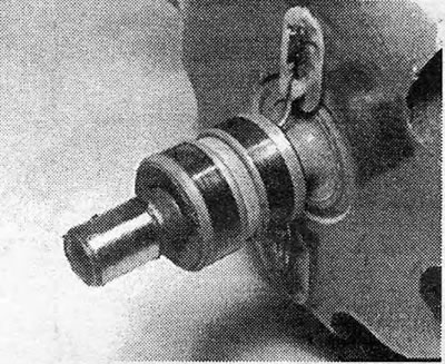
Photo 10.3B Removable generator rings
4. Unscrew the three nuts and washers securing the stator wires to the rectifier and remove the entire stator structure, then unscrew the contact screw and remove the diode bracket (see photo 10.4).
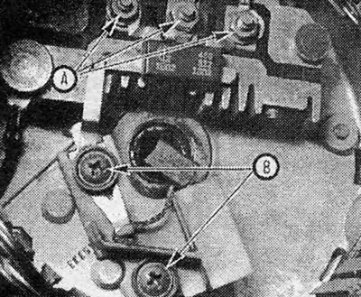
Photo 10.4 Rear surface of the generator: A. Fastening nuts for wires from the stator to the rectifier; B. Brush holder screws
5. Remove the two screws securing the brush holder and voltage regulator to the rear end housing and remove the entire brush holder assembly. Note that there are insulating washers located under the screw heads.
6. Check that the brushes can move freely in their guides and that their length is within the limits specified in the Specifications. If there is the slightest doubt about the condition of the brushes, it is best to replace them with new ones.
7. In order to install new brushes, first unsolder the wires of the old brushes from the holder, and then solder the wires of the new brushes in exactly the same place.
8. Check that the new brushes can move freely in their guides.
9. Before installing the brush holder, hold the brushes in the out position using a piece of stiff wire or a small Allen wrench.
10. Install the brush holder so that the wire protrudes through the slot in the rear housing as shown (see photo 10.10).
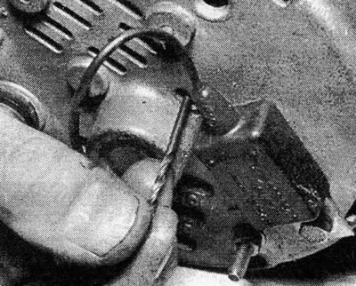
Photo 10.10 Drill used to hold the generator brushes
11. Install the diode bracket and stator into the housing, making sure the stator wires are in the correct position.
12. Assemble the front housing and rotor along with the stator housing, aligning the previously made marks. Insert the three through-mount bolts and tighten them.
13. Now carefully pull the piece of wire out of the slot in the rear casing so that the brushes can fit onto the removable rotor rings.
14. Now the generator can be installed back on the car and its operation can be checked.
15. Remember that if the generator is being replaced with a new or refurbished one, you will need the fan and pulley from the old generator. To release the pulley nut, hold the rotor shaft with an Allen wrench while the nut is unscrewed (see photo 10.15).
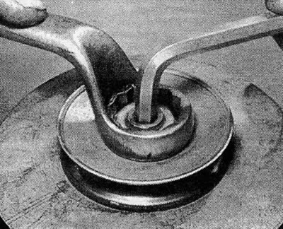
Photo 10.15 Unscrewing the generator pulley nut
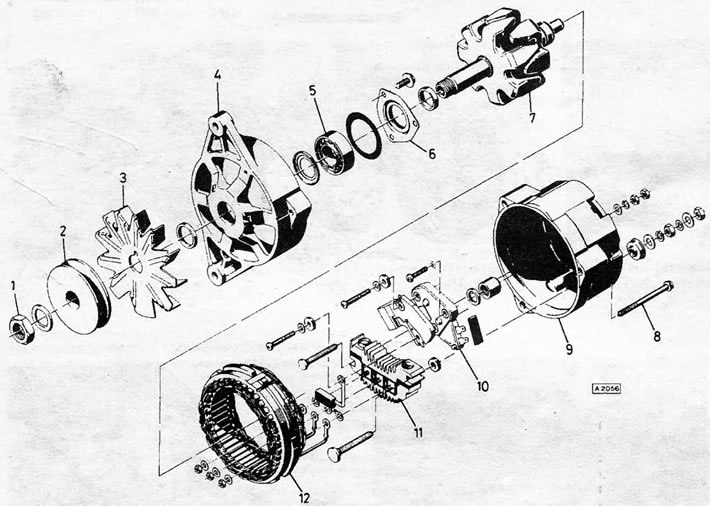
Figure 12.2. Detailed image of Delco-Remy type generator:1. Pulley nut; 2. Pulley; 3. Fan; 4. Drive end housing/bracket; 5. Bearing; 6. Bearing mounting; 7. Rotor; 8. Tie bolt; 9. Bracket - casing with removable rings; 10. Regulator design; 11. Diodes; 12. Stator
Visitor comments