
Bosch type starter motor
2. Remove the two screws and remove the bearing cap from the commutator cover.
3. Remove the clamp from the end of the armature, and, carefully noting the assembly sequence, remove the washers and rubber spacer ring from the armature.
4. Mark the position of the commutator cover in relation to the starter housing, and then remove the two long bolts that hold the entire assembly together. Remove the switch cover.
5. Lift the brush springs so the positive brushes can be released, then remove the brush plate. Mark and remove washers that may be installed there.
6. Disconnect the field winding wire from the solenoid contact, and then unscrew the two mounting screws to disconnect the solenoid from the entire structure. After the solenoid is removed, disconnect its mount from the operating lever.
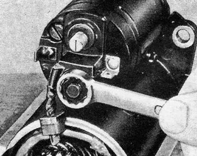
Figure 12.10. Disconnecting the field winding wire from the solenoid contact - Bosch starter
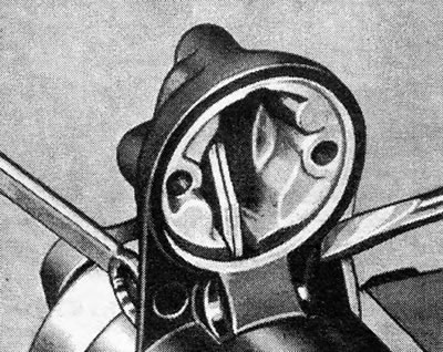
Figure 12.11. Releasing the support spindle of the acting solenoid arm - Bosch type starter
7. Unscrew and remove the operating arm support, then remove the outer frame from the housing structure. Once this is done, remove the rubber plug and the operating lever. Pull the anchor out of the housing.
8. If it is necessary to remove the gear or clutch from the armature, push the retaining ring toward the rear so that the pressure ring can be removed from the shaft. Now you can remove all the parts from the shaft (see Figure 12.12 and 12.13).
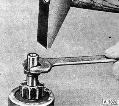
Figure 12.12. Tapping the retaining edge of the clamping ring down along the armature shaft - Bosch type starter
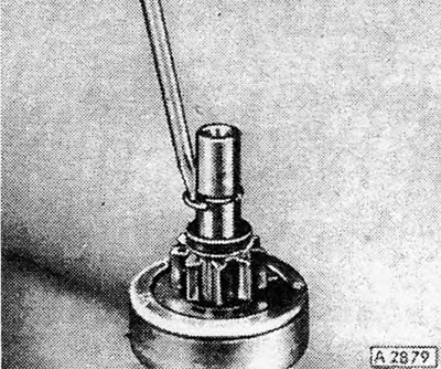
Figure 12.13. Removing the pressure ring from the armature shaft - Bosch type starter
9. Once the starter motor has been disassembled, the various parts can be cleaned and examined for signs of general wear and/or damage. To clean, use a cloth dampened with gasoline, but avoid getting electrical parts wet. Dry all parts thoroughly with a dry, non-fraying cloth.
10. Replace worn or damaged brushes as described in Section 17.
11. If the starter motor tends to get stuck or refuses to disengage from the clutch, it is most likely caused by a condition of the gear. It can also be caused by dirt buildup on the shaft or gear. After removing such dirt, check that the gear can move freely in a spiral along the shaft. If it still tends to get stuck or stick in any way, replace the gear.
12. A badly worn or burnt commutator will require a lathe to finish the surface, but if it is only very dirty or has light marks, it can simply be cleaned with a piece of very gentle sandpaper wrapped around it. If the surface of the commutator requires treatment, this work should be left to a specialist, but ensure that the diameter of the commutator after treatment corresponds to that specified in the Specifications. After processing, the separators should be trimmed using a piece of an old jigsaw, cut to the same thickness as the separators. Trim to a depth of approximately 0.5 to 0.8 mm and then sand with very fine sandpaper. Do not use sandpaper on the commutator as abrasive particles can get into the copper surface and cause rapid wear of the brushes.
13. An anchor with a bent shaft or other signs of damage must be replaced. All electrical inspections should be carried out by a professional equipped with specialized equipment. Although it is possible to perform simple conductivity tests using a light bulb and a low voltage source, more complex tests must still be performed, which are beyond the scope of the DIYer.
14. Assembling the starter motor is carried out by performing the above steps in reverse order, however, some details should be noted:
- A) After assembling the clutch and gear, install the retaining ring on the armature shaft using a new clamping ring;
- b) Make sure all washers and gaskets are installed in the correct order;
- V) When installing the cover on the end frame, align the tab with the slot;
- G) Make sure the carbon brushes can move freely in their guides;
- d) Lightly lubricate all sliding parts, including the armature helix pin, the operating arm sliding surfaces, the clutch bearing surfaces, and the armature bearings. Of course, not a drop of oil should get on the commutator or brushes.
Delco-Remy type starter motors
15. Mark the position of the commutator cover and drive end bearing housing in relation to the starter housing to ensure proper assembly, and then disconnect the field winding wires from the lower solenoid boss.
16. Unscrew and remove the two connecting bolts from the switch cover and remove the cover. Carefully remove the starter housing from the armature and drive bearing housing (see photo 18.16).
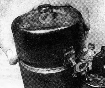
Photo 18.16 Removing the back cover (Delco-Remy)
17.Unscrew the two mounting screws and remove the solenoid and its spring from the drive bearing housing. Remove the clamp from the operating lever spindle and tap the spindle out of the housing. This will allow the anchor and the operating lever to be removed together, and then this lever can be disconnected from the anchor structure.
Photo 18.17A Removing the starter solenoid and spring (Delco-Remy)
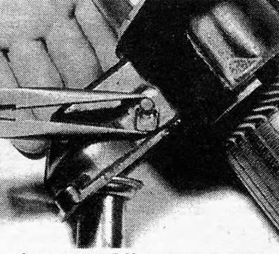
Photo 18.17B Installing the support spindle clamp (Delco-Remy)
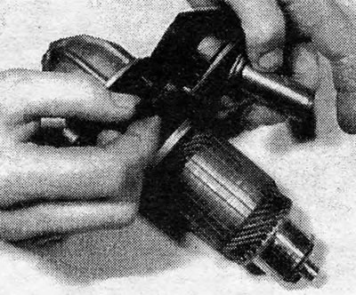
Photo 18.17 C Removing the support spindle (Delco-Remy)
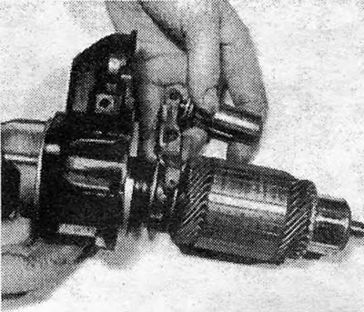
Photo 18.17D Disassembling the drive end housing (Delco-Remy)
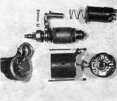
Photo 18.17E Detailed image of the Delco-Remy starter motor
18. The remainder of the disassembly and subsequent reassembly process for this starter is exactly the same as described in paragraphs 8 to 14, which are now recommended to be addressed. Once the solenoid is installed in the drive bearing housing, use a small amount of hardening plastic putty to seal the slot in the housing to prevent water from entering the starter. Then continue assembly as described above.
Visitor comments