
OpelBook.ru
Cars AvtoVAZ Cars Mitsubishi Cars BMW Cars Mercedes Cars Nissan Cars Toyota Cars Chevrolet
English Русский
Български
Беларускі
Український
Српски
Hrvatski
Română
Polski
Slovenský
Magyar
 |  Sitemap  |  Contacts  |    


Main Astra Corsa Insignia Kadett Omega Vectra Zafira Others Articles
Frontera A (1991-1998, petrol) Frontera B (1998-2004) Ascona C (1981-1988) Vivaro A (2001-2014)
  • Main
  • Opel
  • Ascona C
  • Electrical equipment
  • Power devices
  • Starter Motor Brushes — Checking and Replacing

Starter Motor Brushes — Checking and Replacing (Opel Ascona C)

            0

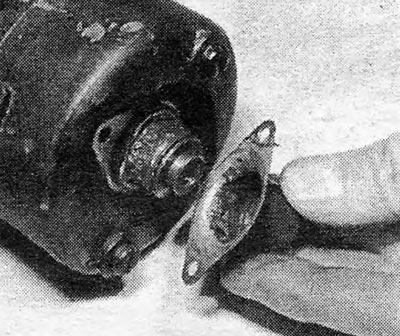
1. Once the starter is removed from the engine and placed on a clean, level surface, begin by removing the cap from the end where the armature is located, which is held in place by two small screws at the end of the motor. Remove the anchor retaining clip, washers and rubber washers that are on the outside. Loosen and remove the two long bolts that hold the entire motor assembly together. The end cap can now be removed to gain access to the brushes and mounting plate (see photo 17.1 A, B, C and D).

Photo 17.1A Anchor end cap (Bosch)
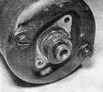
Photo 17.1A Anchor end cap (Bosch)


Photo 17.1B Starter anchor clamp (Bosch)
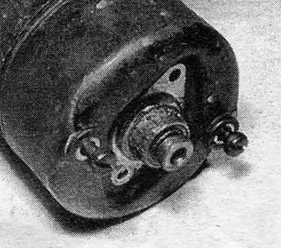
Photo 17.1B Starter anchor clamp (Bosch)
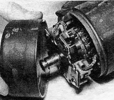

Photo 17.1B Starter anchor clamp (Bosch)

Photo 17.1B Starter anchor clamp (Bosch)


Photo 17.1D Removing the starter motor cover (Bosch)

Photo 17.1D Removing the starter motor cover (Bosch)


2. Remove the brushes from the holder and then remove the holder from the armature shaft. Remove the spacer washers installed between the brush plate and the armature block (see photo 17.2).
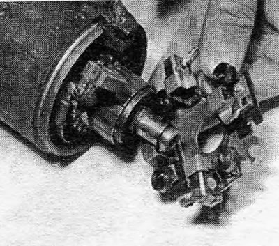
Photo 17.2 Removing the brush plate holder (Bosch)

Photo 17.2 Removing the brush plate holder (Bosch)


(Material published on the website www.opelbook.ru)

3. Check the condition of the brushes: if they are worn to the extent that their length is less than the minimum length specified in the Specifications, they should be replaced. New brushes that meet the latest standards do not have shunt wires, so when installing this type of brushes, you must first break off the old ones with a vice or hammer to remove all the carbon from the shunt wire, and then completely strip the wires to prepare them for soldering. Insert the wire into the hole in the new brush and spread it out so that it fills the entire hole. Hold the wire as close to the brush as possible with pliers to ensure that the wire is in the correct position when soldering, and also to prevent the soldering iron from pushing the wire further than necessary, which will affect the flexibility of the wire. For this job you will need a pencil type soldering iron with a power of 12 to 15 watts. After soldering the wire in place, remove all excess solder with a file, and check that the brush can move freely in its guide (see photo 17.3).
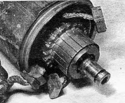


Photo 17.3 Commutator and brushes of the field coils of the Bosch type starter motor

Photo 17.3 Commutator and brushes of the field coils of the Bosch type starter motor


4. Wipe the starter motor anchor and commutator clean with a piece of cloth soaked in gasoline.

5. Install the brushes into the holder and then place the holder onto the armature shaft, remembering to install two washers between the holder and the armature (see photo 17.5).
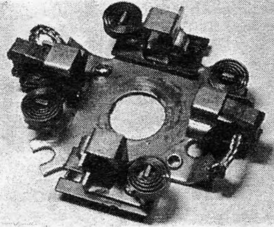
Photo 17.5 Bosch type starter brush holder plate

Photo 17.5 Bosch type starter brush holder plate


6. Install the back cover and secure it with two long bolts.

7. Install the armature shaft end cover after installing the rubber seal ring, washer and shaft clamp.

Delco-Remy type


8. After removing the motor from the engine, place it on a clean and level surface, unscrew and remove the two through-mount bolts from the rear cover. Also remove the two small screws that secure the brush holder.


9. Remove the rear cover, noting exactly how it is installed in relation to the wires coming from the solenoid. Reinstall the bearing sleeve if it has come loose; usually it should remain in the lid.

10. Remove the positive brushes (those connected to the field windings) from the holder, being careful not to damage the springs. Disconnect the brush holder from the motor.

11. Replace brushes if they are worn to the extent that their length is less than the minimum length specified in the Specifications. Always replace all four brushes at the same time.

12. Replace the negative brushes (those that are attached to the holder) by soldering off the old ones and soldering new ones in their place. Hold the brush wires with pliers to prevent solder from getting on them and causing them to lose their flexibility.

13. Replace the positive brushes by cutting the old ones at a suitable distance from the field windings. Solder the wires of the new brushes to the old ones, again making sure that no solder gets on the wires or brushes.

14. Clean the commutator with a non-shedding cloth soaked in gasoline. Make sure the brushes can move freely in their guides.

15. Insert the negative brushes into their holders, placing the springs on the sides of the brushes so that the brushes are not yet fully lowered into place.

16. Prepare the brush holder for installation in the motor. Insert it into place and hold the positive brushes in a similar manner.

17. Carefully lift the spring of each brush so that it rests on the back of the brush; now the brushes will take their normal position.


18. Install the bearing sleeve and rear cover, making sure that the screw holes in the cover and brush holder are aligned. Insert and tighten the brush holder mounting screws.

19. Install and tighten the motor through-mount bolts.


This article is available at russian, bulgarian, belarusian, ukrainian, serbian, croatian, romanian, polish, slovak, hungarian
Checking the article: Kornev Georgy

Share information:

Previous articles
Opel Ascona C: Power devices
Next articles

Starter Solenoid — Removal and Installation
Starter Repair — General Information
Starter motor — removal and installation
Starter Motor — Checking in a Car
Starter Motor — General Description
Generator brushes (Bosch type) — checking, removal and installation
Starter motor — disassembly and assembly


See similar ones from other Opel car manuals:
▶ Checking the condition and replacing the brushes Opel Corsa B (1993-2000)
▶ Removal and installation the voltage regulator, checking… Opel Vectra C (2002-2008)
▶ Starter motor — removal and installation Opel Astra F (1991-1998, petrol)
▶ Checking, adjusting and replacing the throttle position… Opel Kadett D (1979-1984)
▶ Starter — Checking in a Car Opel Omega A (1986-1993)
Link to this page in different formats

Visitor comments


No comments yet


How much will 47 + 37 =


Vivaro A (2001-2014) 
  • General information
  • User manual
  • Power unit
  • Petrol engine F4R
  • Diesel engine F9Q
  • Diesel engine G9U
  • Transmission
  • Clutch and drive shafts
  • Manual gearbox
  • Chassis
  • Front suspension
  • Rear suspension
  • Brake system
  • Body
  • Exterior
  • Interior
  • Electrical equipment
  • Heating and ventilation
  • Air conditioner
  • Equipment and devices
  • Electrical diagrams
Ascona C (1981-1988) 
  • General information
  • Maintenance
  • Power unit
  • Gasoline engines
  • Diesel engines
  • Cooling system
  • Fuel and exhaust system
  • Contact ignition system
  • Contactless ignition system
  • Transmission
  • Clutch
  • Mechanical gearbox
  • Automatic gearbox
  • Drive shafts
  • Chassis
  • Steering
  • Brake system
  • Car suspension
  • Body
  • Exterior
  • Interior
  • Doors and windows
  • Electrical equipment
  • Equipment and devices
  • Power devices
  • Electrical circuits
Frontera B (1998-2004) 
  • General information
  • User manual
  • Maintenance
  • Power unit
  • Petrol engines 2.2 l
  • Petrol engines 3.2 l
  • Diesel engines 2.2 l
  • Cooling system
  • Fuel system (petrol)
  • Fuel system (diesel)
  • Ignition system
  • Transmission
  • Clutch
  • Manual gearbox MUA5C
  • Automatic gearbox 4L30E
  • Chassis
  • Suspension and axles
  • Steering
  • Brake system
  • Body
  • Exterior
  • Interior
  • Doors, locks and windows
  • Heating and air conditioning
  • Electrical equipment
  • Power devices
  • Equipment and devices
  • Lighting and signaling
  • Electrical diagrams
Frontera A (1991-1998, petrol) 
  • General information
  • Introduction to guide
  • User manual
  • Maintenance
  • Power unit
  • Engine repair
  • Lubrication system
  • Cooling system
  • Power and exhaust system
  • Engine electrics
  • Transmission
  • Clutch
  • Mechanical gearbox
  • Cardan shafts
  • Chassis
  • Brake system
  • Front suspension
  • Rear suspension
  • Steering
  • Body
  • Repair and care
  • Electrical equipment
  • Equipment and devices
  • Electrical circuits
OpelBook.ru © 2017–2026 · Mobile version · · Sitemap: EN BG BY UA RS HR RO PL SK HU · Feedback · Site search
Astra F, petrol · Astra G, petrol · Astra G · Astra H · Astra J, petrol · Corsa B · Corsa C, petrol · Corsa C · Insignia A · Kadett D · Kadett E · Omega A · Omega B · Omega B2 · Vectra A, petrol · Vectra A · Vectra B, petrol · Vectra B · Vectra C · Zafira A, petrol · Frontera A, petrol · Frontera B · Ascona C · Vivaro A ·
We want your visit to be comfortable 🤝! We use cookies 🍪 to make that happen.