
2. Remove the traction relay as described in Chapter 13. Loosen the two screws and remove the end cap from the switch bezel.
3. Using a lever, remove the bracket at the end of the armature and, remembering the assembly sequence, remove the gaskets and rubber O-ring from the armature.
4. Mark the position of the switch housing relative to the starter housing, then remove the two long bolts that hold the housing assembly together. Remove the switch cover.
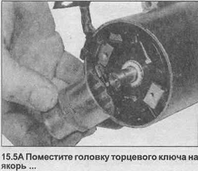
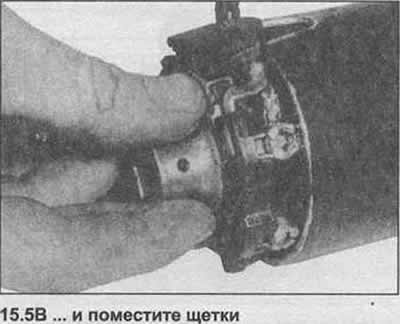
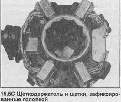
5. Raise the brush springs and remove the mounting plate. Locate and remove all gaskets. You can use a large diameter head to secure the brushes in their holders before installation (photo).
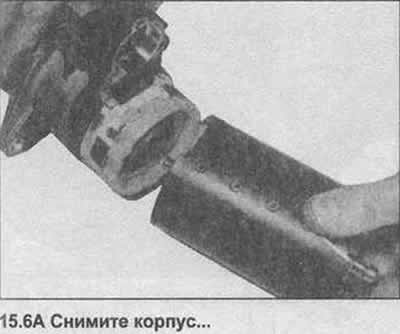
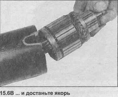
6. Remove the body together with the anchor, then pull out the anchor (photo).
7. Where installed, unscrew the drive arm support.
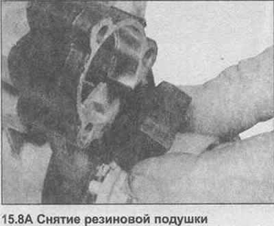
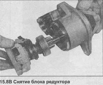
8. Use the lever to remove the rubber cushion and remove the gear unit from the drive housing (photo).
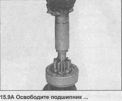
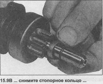
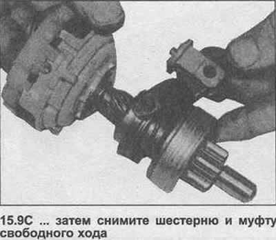
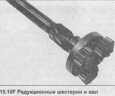
9. To remove the gear and freewheel, pull back the bearing and remove the circlip (photo).
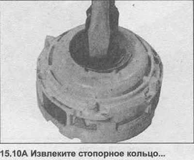
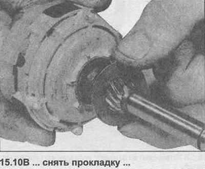
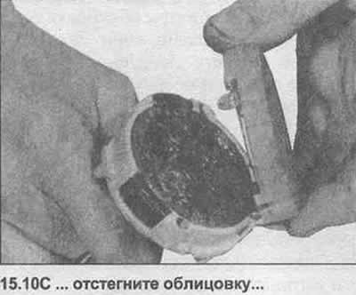
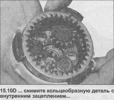
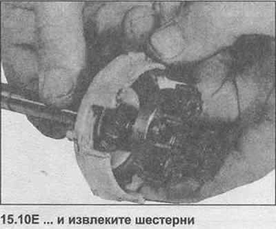
10. To disassemble the gear unit, remove the retaining ring, remove the gasket, unfasten the lining, remove the ring-shaped part and remove the mechanisms (photo).
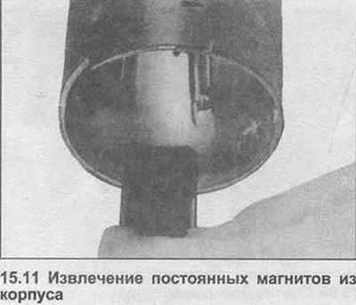
11. If necessary, remove the permanent magnets from the housing (photo).
12. With the starter motor removed, the various components can be cleaned and inspected for signs of general wear and/or damage. Use a cloth dampened with gasoline for cleaning, but do not wet electrical components.
13. Replace worn or damaged carbon brushes as shown in Chapter 14.
14. If the starter sticks or does not disengage well, then the cause is most likely in the gear. The accumulation of dirt on the shaft or on the gear can also lead to this. After removing all the dirt, check that the gear is free to spiral along the shaft. If the starter still sticks or sticks, replace the gear.
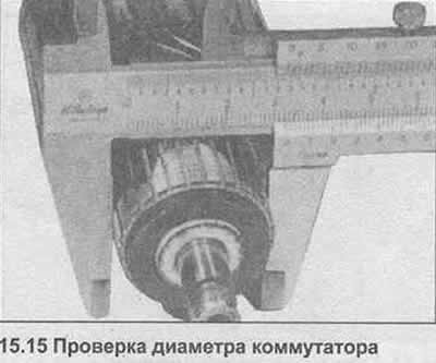
15. A severely worn or burnt commutator must be machined on a lathe. With a small amount of soot or oiling, it can be processed with a piece of sanding paper. When processing the commutator, ensure that the minimum diameter is maintained within the limits specified in the Specifications (photo). After grinding, it is necessary to cut through the separators (separators), using a piece of an old hacksaw blade to the same thickness as the dividers (separators). The depth of the slot should be approximately 0.5-0.8 mm. Then grind the grooves with fine sandpaper, do not use emery, as its particles can get on the copper parts and cause rapid wear of the brushes.
16. An anchor with a bent shaft or other signs of damage should be replaced. A complete check of the electrical part must be carried out on special equipment.
17. Starter assembly is carried out in the reverse order to disassembly, but subject to the following points:
- a) After installing the clutch and gear on the armature shaft, install the retaining ring using a new ferrule and then reinstall the retainer
- b) Make sure all washers and gaskets are installed in the correct order
- c) Align the tab and groove on the cover and casing
- d) Make sure the carbon brushes move freely in their guides.
- e) Lightly lubricate all moving parts, including armature spiral groove, drive, mating surfaces, clutch bearing running surfaces and armature bearings. Of course, the grease must not contaminate the commutator or brushes.
Visitor comments