
General information
1. The vehicles in question use an alternator. When installing additional electrical equipment, check that the generator has enough power to provide electricity to new consumers.
2. The generator is driven by a multirib belt from the engine crankshaft.
3. The generator is an electrical machine with electromagnetic excitation. A rectifier is built into the generator to convert AC to DC. The output voltage is regulated by a built-in regulator.
4. When the generator is running, the electric current flowing through the field winding creates a magnetic flux around the rotor poles. When the rotor rotates, its magnetic poles periodically change under each stator tooth, as a result, the magnetic flux passing through the teeth continuously changes in magnitude and voltage. This variable magnetic flux creates an electromotive force in the stator winding (EMF).
5. At a high rotor speed, when the output voltage of the generator begins to exceed 13.6-14.5 V, the voltage regulator is locked, and the current does not pass through the field winding. When the voltage drops, the regulator opens again, allowing free flow of current through the field winding. The higher the rotor speed, the longer the regulator remains locked and, accordingly, the voltage at the generator output decreases more. The process of locking and unlocking the regulator occurs at a high frequency, so the output fluctuations remain almost imperceptible and the generator voltage can be considered constant, maintained at a level of 13.6-14.5 V.
6. The charging system does not require periodic maintenance, however, the condition and replacement of the alternator drive belt, battery and its wiring should be done on a regular basis in accordance with the maintenance schedule (see chapter 1).
7. The serviceability of the charge system is monitored using the corresponding lamp on the instrument cluster (see chapter «Controls and methods of operation», Section 16).
Generator Maintenance Safety Measures:
- Do not disconnect the battery or voltage regulator while the engine is running;
- Do not ground the generator excitation terminal or the cable attached to it;
- Do not confuse the order of connecting the voltage regulator wiring;
- When charging the battery without removing it from the car, make sure that both wires are disconnected from it;
- Remember that the inclusion of a voltage regulator closed to ground leads to its instantaneous failure;
- Never remove the generator with the battery connected;
- Never use voltage meters or test lamps connected to a household network when checking on-board electrical equipment (110/220V);
- When checking the condition of the diodes, do not apply a voltage of more than 12 V to them and do not use megohmmeters, which also have a high output voltage - breakdown of the diodes will lead to a short circuit. Remember that when checking the insulation of the electrical wiring with a megohmmeter, it is necessary to disconnect all electrical wiring from the generator;
- Before carrying out any electric welding work on the car, do not forget to disconnect the electrical wiring from the generator and battery;
- Any checks of circuits and on-board wiring assemblies should be carried out with the engine off and the battery disconnected;
- Remember that reversing the polarity of any connections carries the risk of permanent damage to the rectifier and generator voltage regulator.
Alternator voltage test
8. If the battery does not charge or is not sufficiently charged while driving, check the alternator voltage.
9. Connect a voltmeter between the positive and negative battery terminals and start the engine. The voltage at start should drop to about 8 volts (at ambient temperature +20°С).
10. Increase the engine speed to 3000 rpm - if the generator and regulator work properly, the voltage at the terminals should be from 13 to 14.5 V.
11. To check the stability of the voltage, turn on the high beam and repeat the measurements at 3000 / min. The measured voltage should not increase by more than 0.4 V from the previously measured values.
12. If the indicators are outside the nominal value, the generator and regulator must be checked in a specialized workshop.
Removal and installation
Z14XEP engine
13. Remove the multirib belt (see chapter 2).
14. Loosen the 2 fixing nuts and disconnect the generator lead wire.
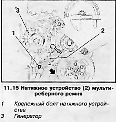
15. Remove the bolt (see resist. illustration) fastening the multirib belt tensioner and press the tensioner (see arrow) to release access to the lower generator mounting bolt.
16. Release nuts of the top and bottom bolt fastening of the generator, take bolts and remove the generator.
17. Installation is made in an order, the return to removal.
Z16XEP engine
18. Remove the multirib belt (see chapter 2).
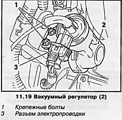
19. Disconnect the wiring connector and traction from the vacuum regulator (see resist. illustration), turn out 2. fixing bolts and remove a regulator.
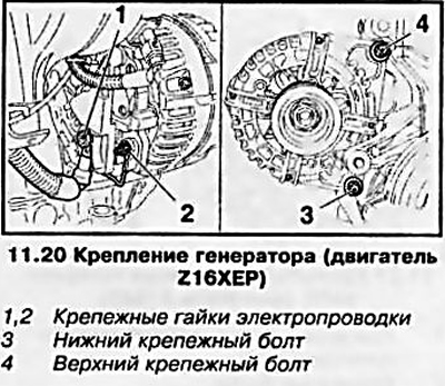
20. Raise the car on a lift, loosen the 2 fixing nuts (see resist. illustration) and disconnect the generator lead wire.
21. Turn out the bottom bolt of fastening of the generator, lower the car, turn out the top bolt and remove the generator.
22. Installation is made in an order, the return to removal.
Z18XE engine
23. Remove the multirib belt (see chapter 2).
24. Disconnect the wiring connector (see resist. illustration) from the camshaft sensor, remove the upper alternator mounting bolt, loosen the lower mounting bolt and feed the alternator back.
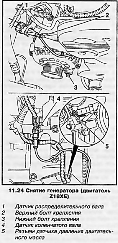
25. Disconnect the wiring connector (see illustration 11.24) from the crankshaft sensor, disconnect the engine oil pressure sensor connector and release the cable from the mounts.
26. Remove the multirib belt tensioner from the generator support.
27. Loosen 2 fixing nuts (see resist. illustration) and disconnect the supply wiring from the generator, unscrew the 3 mounting bolts and remove the generator together with the mounting bracket.
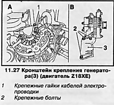
28. Installation is made in an order, the return to removal. In this case, the sleeve of the tensioner of the multi-ribbed belt must coincide with the hole in the generator support.
Z20LE engine (L/R/H)
29. Remove the multirib belt (see chapter 2).
30. Remove mounting brackets (see resist. illustration) generator, turn out 2 fixing nuts and disconnect the bringing electroconducting from the generator.
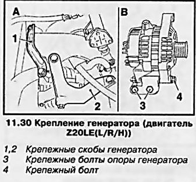
31. On Astra models, 2 fixing bolts must be unscrewed (3) (see resist. illustration) and remove the alternator in an upward direction.
32. On Zafira models: Loosen the bolt (see illustration 11.30) mounting the generator and feed the generator back. Raise the vehicle on a lift and remove the 2 alternator mounting bolts. Lower the vehicle, disconnect the fuel line from the generator support and remove the generator.
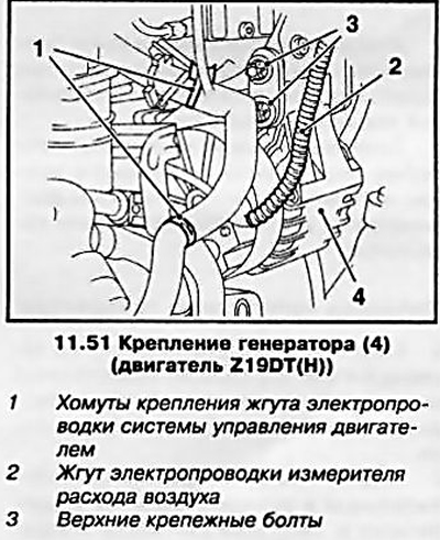
33. Installation is carried out in the reverse order.
Z22YH engine (Zafira)
34. Remove the multirib belt (see chapter 2).
Note: The belt is removed from below.
35. Disconnect the generator wiring connector, remove the 2 lower generator mounting bolts, lower the vehicle and remove the 2 upper mounting bolts.
36. Press a hose of system of cooling aside and remove the generator in an upward direction.
37. Installation is carried out in the reverse order.
38. Remove the multirib belt (see chapter 2).
39. Release 3 fixing nuts and disconnect electroconducting from the generator.
40. Turn out the top and lower fixing bolts and remove the generator.
41. Installation is carried out in the reverse order.
Z17DT engine (L/H)
42. Remove the multirib belt (see chapter 2).
43. Remove the klaxon horn (see chapter 12).
44. Disconnect the vacuum lines (see resist. illustration) brake booster and solenoid valve from the vacuum pump, disconnect from the pump.
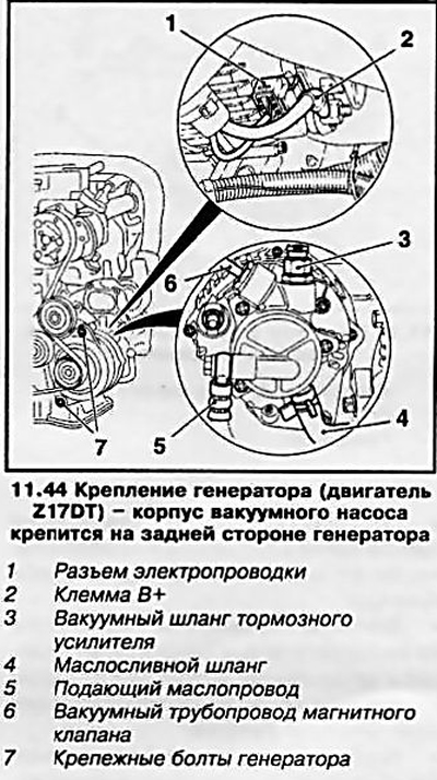
45. Place a suitable container under the vacuum pump. Remove hollow bolt (see illustration 11.44) and disconnect the oil supply line from the vacuum pump, then loosen the clamp and disconnect the oil drain hose.
46. Loosen the fixing nut (see illustration 11.44), disconnect the terminal (B+), and then the wiring connector (D+) from the generator. Turn out 2 fixing bolts and remove the generator.
47. Installation is carried out in the reverse order of removal. Before connecting the oil supply line, be sure to replace the O-ring.
Z19DT engine (L/H)
48. Remove the multirib belt (see chapter 2).
49. Remove the bolt (see resist. illustration) mount the generator and lower the vehicle.
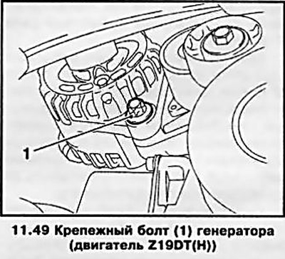
50. Remove the fuel filter housing from the mounting clamp and remove the last (see Chapter 4, Section 10).
51. Release wiring harnesses (see resist. illustration) engine control system and air flow meter from the mounting clamps, and disconnect the electrical wiring connector of the meter.
52. Turn out 3 fixing nuts and disconnect an electroconducting from the generator, then turn out 2 top bolts (see illustration 11.51) mounting bracket and remove the alternator.
53. Installation is carried out in the reverse order of removal. The top fixing bolts must be tightened after installing the multi-ribbed belt.
Visitor comments