
General information
1. The sole purpose of the starting system is to ensure that the engine rotates at a speed sufficient to start it - approximately 300 rpm.
2. The starting system consists of a starter, battery, ignition switch, traction relay and connecting wiring.
3. The starter is a mixed-excitation DC electric motor with an externally mounted electromagnetic traction relay. The starter consists of a housing or a stator with excitation windings, an armature with an overrunning clutch, a cover with brush holders and a traction relay.
4. When the starter is turned on, current from the battery begins to flow through the winding of the traction relay. The relay armature is pulled in and the contacts are closed. At the same time, the relay armature through the drive lever ensures the extension of the gear with the overrunning clutch, while the clutch hub rotates on the screw splines of the starter armature shaft and also turns the gear, which facilitates the engagement of the latter with the flywheel ring gear. A current passes through the closed contacts of the traction relay, which feeds the stator and armature windings, and the starter armature begins to rotate together with the hub and freewheel.
5. After starting the engine, the speed of the gear exceeds the speed of the starter armature. In this case, the overrunning clutch turns freely, and torque is not transmitted from the engine flywheel to the starter armature shaft. After releasing the ignition key, the power circuit of the windings of the traction relay opens through the ignition switch, the armature of the traction relay is pressed back to its original position by a spring, the relay contacts open and the drive gear disengages from the flywheel ring gear.
6. A starter with a retractor is located parallel to the engine crankshaft and is fixed to the power unit.
7. When carrying out maintenance, it is necessary to ensure an impeccable connection of the electrical wiring, remove traces of corrosion on the clamp and lubricate the terminals with special grease.
Removal and installation
Z14XEP engine
8. Disconnect the wire from the negative terminal of the battery (see Section 9).
9. Raise the car on the lift, loosen the nut (see resist. illustration) and disconnect the ground cable at «mass».
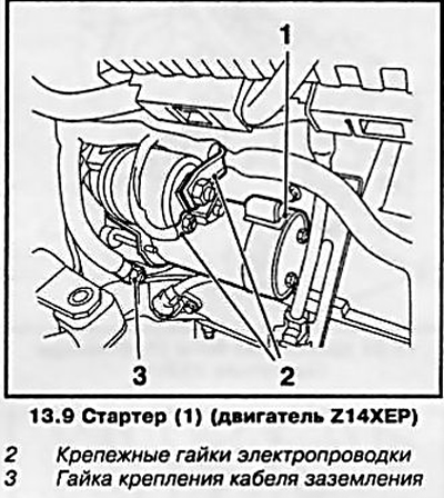
10. Loosen the fixing nuts (see illustration 13.9) and disconnect the electrical wiring from the starter, then remove the 2 mounting bolts and remove the starter.
11. Installation is carried out in the reverse order.
Z18XE engine
12. Disconnect the wire from the negative terminal of the battery (see Section 9) and raise the car on a lift.
13. Remove the protective bracket (see resist. illustration) the exhaust pipe of the exhaust system.
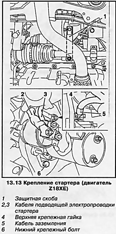
14. Loosen 2 fixing nuts (see illustration 13.13) and disconnect the lead wire from the starter, as well as the ground cable.
15. Loosen the top fixing nut and the bottom fixing bolt (see illustration 13.13) and remove the starter.
16. Installation is carried out in the reverse order.
Z16XEP engine
17. Disconnect the wire from the negative terminal of the battery (see Section 9).
18. Disconnect the vacuum hose (see resist. illustration), remove the 2 bolts and remove the intake duct support, then loosen the nuts and disconnect the wiring cables.
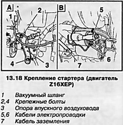
19. Disconnect the ground cable (see illustration 13.18), remove the 2 mounting bolts and remove the starter.
20. Installation is carried out in the reverse order.
Z22YH engine (Zafira)
21. Disconnect the wire from the negative battery terminal (see Section 9) and raise the car on a lift.
22. Loosen the 2 nuts and disconnect the wiring cables from the starter.
23. Turn out 2 fixing bolts (see resist. illustration) and remove the starter.
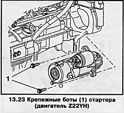
24. Installation is carried out in the reverse order.
Z20LE engine (L/R/H)
25. Disconnect the wire from the negative terminal of the battery (see Section 9).
26. Turn out 2 fixing bolts and disconnect a bracket of fastening of a vacuum receiver from an inlet air line and from the block of the engine.
Note: The reservoir is mounted at the rear top of the cylinder block.
27. Loosen 2 nuts and disconnect cables (see resist. illustration) electrical wiring from the starter, remove the 2 mounting bolts and remove the starter.
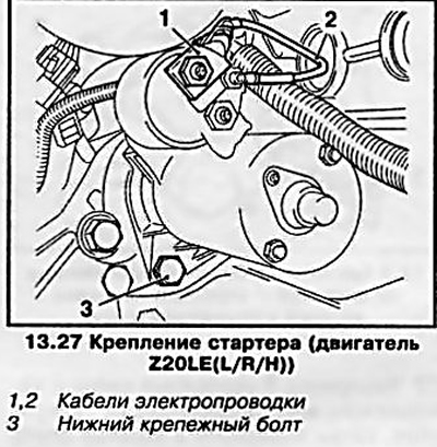
Note: The bolts have different lengths - the top mounting bolt is longer.
28. Installation is carried out in the reverse order.
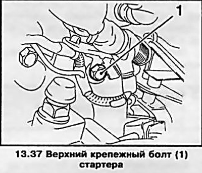
Z13DTH engine
29. Remove the battery from the tray (see Section 9).
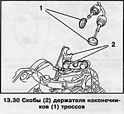
30. Use an open-end wrench to wring out the tips (see resist. illustration) cables from ball joints on the gearbox. At the Opel service station, a special device is used for this (lever arm) Orel-KM-6042. Pull back the latches and remove the tips from the brackets of the holder and take them aside, be careful the tips and cables should not be twisted, stretched or bent.
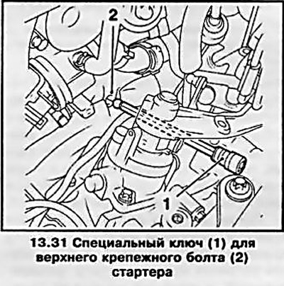
31. Special long key (see resist. illustration) remove the top starter mounting bolt, and then raise the car on a lift.
32. Disconnect 2 hoses from the vacuum reservoir (see resist. illustration).
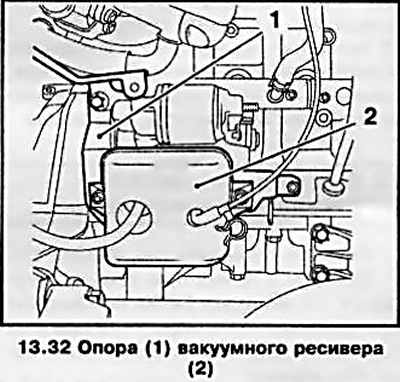
33. Loosen the nut and disconnect the ground cable from the starter, unscrew the 2 bolts and remove the vacuum reservoir with the support (see illustration 13.32).
34. Loosen the 2 nuts and disconnect the wiring cables from the starter, unscrew the lower starter mounting bolt and remove the starter.
35. Installation is made in the reverse order of removal. The lower starter mounting bolt should be tightened after the upper bolt has been tightened.
Z17DT engine (L/H)
36. Remove the battery and battery tray (see Section 9).
37. Turn out the top fixing bolt (see resist. illustration) starter from the gearbox housing.
Note: The starter is located at the rear of the engine block.
38. Raise the car on a lift and remove the crankcase protection (see chapter 2).
39. Disconnect the oil filter drain hose from the engine block by loosening the clamp.
40. Disconnect the tie (see resist. illustration), remove the fixing bolt and nut, and disconnect the starter wiring cables.
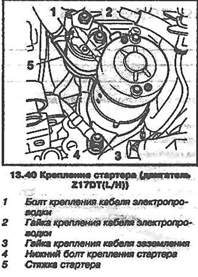
41. Loosen the nut securing the earth cable (see illustration 13.40), turn out the bottom fixing bolt and remove a starter.
42. Installation is carried out in the reverse order.
Z190T engine (L/H)
43. Disconnect the wire from the negative terminal of the battery (see Handed out 9).
44. Remove the engine cover, and on Zafira modems equipped with Z19DT / Z19DTL engines, also remove the fairing grille and the cover of the rear bulkhead of the engine compartment (see chapter 11).
45. Release the hose (see resist. illustration) cooling system from the holder, loosen 2 nuts and disconnect the holder of the wiring harness, take the harness to the side.
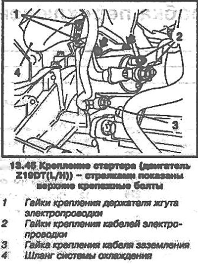
46. Loosen 2 nuts (see illustration 13.45) and disconnect the wiring cables from the starter, then remove the 2 upper starter mounting bolts.
47. Raise the car on a lift and remove the crankcase protection (see chapter 2), loosen the fixing nut and disconnect the ground cable, unscrew the bottom fixing bolt and remove the starter.
48. Installation is carried out in the reverse order.
Check of a condition and recovery repair of a starter
49. Performing a detailed diagnosis of the condition and restoring the starter should be entrusted to car service specialists - first make sure that the cost of the repair does not exceed the price of a new starter.
Visitor comments