
General information
1. Top dead center (TDC) is the highest point of the piston stroke in its cylinder. In 4-stroke engines, during the rotation of the crankshaft, each of the pistons reaches this position twice during one operating cycle: once at the end of the compression stroke and the second at the end of the exhaust stroke. Determination of the exact position of the TDC of the piston at the end of the compression stroke (usually the first cylinder) is of great importance for many subsequent work, for example, to replace the toothed belt, check the valve timing and replace the cylinder head gasket. Sometimes the TDC of the compression stroke is also called the ignition timing.
Note: Cylinder numbers are counted in sequence from 1 to 4. The first cylinder is on the accessory drive/timing side.
2. Checking and adjusting the valve timing is a very laborious operation and can only be performed using a special tool from Opel, make sure in advance that all the necessary accessories are available and at hand. This tool is usually only available at a service station.
3. To bring the piston of the first cylinder to TDC, turn the crankshaft evenly and slowly so that the TDC marks match. Depending on the conditions, cranking the engine crankshaft can be performed in the following ways:
- Hang one of the front wheels and put the car on a stand. Engage 5th gear - when turning the suspended wheel, the engine crankshaft will turn (models with manual transmission). Use an assistant to turn the wheel when making adjustments.
- If you don't have jacking tools handy, choose a flat, large enough area and engage 5th gear. When moving the car by pushing, the crankshaft will also turn (models with manual transmission).
- In stationary conditions, the crankshaft is rotated using a ratchet and changing the head («E18»), which is installed on the central bolt of the crankshaft pulley, while the neutral gear must be engaged and the parking brake cocked. The crankshaft must be turned clockwise (viewed from the timing side).
Attention: Do not turn the engine by the camshaft gear bolt - this will tighten the toothed belt / timing chain (timing)!
4. Before starting work on setting the TDC, disconnect the wire from the negative terminal of the battery (see chapter 5) and remove the air cleaner (see chapter 4).
Note: On models since 2004 with ESP, a steering wheel angle sensor is mounted on the steering column. After each disconnection of the battery at the end of work, it is imperative to reprogram this device using special devices.
Z10XE engines (P) /Z12XE/Z14XEP
Examination
5. Disconnect the wiring connectors of the camshaft sensor, engine oil pressure switch and coolant temperature sensor. Separate the cable duct on the right side of the engine and take it to the side. Disconnect 2 crankcase ventilation hoses (PCV) and remove the ignition module (see chapter 5). Turn out 13 bolts of fastening of a cover of a head of cylinders and remove it.
6. Raise the car on a lift or place it on stands. Remove the multi-ribbed belt cover, and on Corsa-Eco models, remove the crankcase guard (see Section 5).
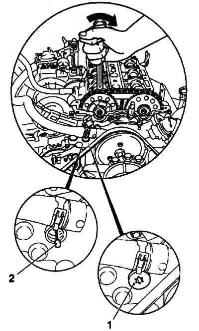
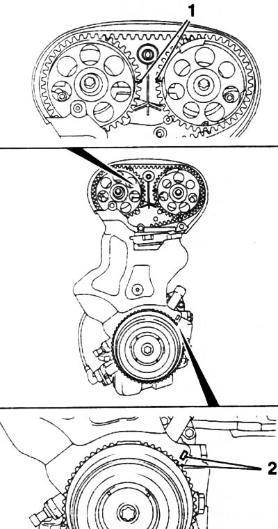
7. Rotate the crankshaft in the direction of engine rotation (clockwise) so that the mark on the shaft pulley coincides with the tide on the timing cover (timing) (see resist. illustration).
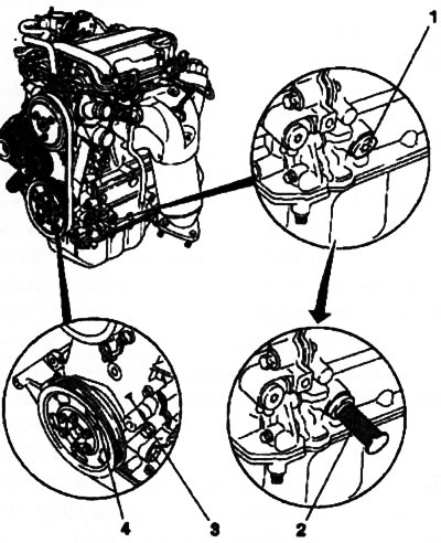
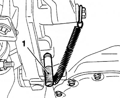
6.7. When setting TDC marks (3 and 4) must match (Z10XE engines (P) /Z12XE/Z14XEP): 1. Crankshaft blocking hole plug; 2. Installed fixture KM-952
8. In the TDC position of the compression stroke, the camshafts of the first cylinder should be turned outward from the center of the engine (see resist. illustration). Otherwise, rotate the crankshaft one more full turn.
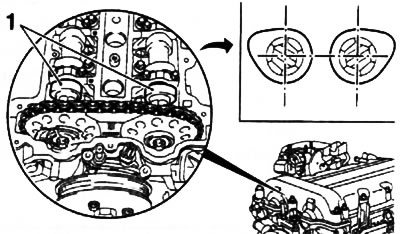
6.8. At TDC on the compression stroke, the cams (1) camshafts must be symmetrically turned outward (Z10XE engines (P) /Z12XE/Z14XEP)
9. To check the position of the TDC with the help of special tools, do not bring the crankshaft to the alignment of the marks by about 15-20°and unscrew the plug that closes the crankshaft lock hole (see illustration 6.7).
10. Install the KM-952 tool in the hole (see illustration 6.7), slowly and smoothly turn the crankshaft until the tool enters the special groove of the crankshaft (will fix the shaft) - in this case, the marks on the crankshaft pulley and on the timing cover must match, and the timing cams above the first cylinder must take the appropriate position (see above).
11. Install in the grooves of the camshafts (flywheel side) special device KM-953 (see resist. illustration) - the protrusions of the device must enter the grooves to the greatest possible depth. If it is not possible to install the device, it is necessary to adjust the valve timing (see below).
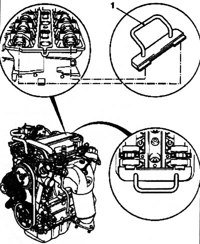
6.11. Installing the KM-953 fixture (1) (Z10XE engines (P) /Z12XE/Z14XEP)
12. Install special tool KM-954 (see resist. illustration) so that the protrusion of the tool falls into the notch of the rotor of the camshaft sensor. If the protrusion and recess do not match, adjust the valve timing (see below).
6.12. Installing KM-954 (1) (Z10XE engines (P) /Z12XE/Z14XEP): 2. Rotor camshaft sensor shaft
Adjustment
13. At the end of the check, remove the KM-953 and KM-954 fixtures from the engine. Caution: Under no circumstances should control devices be used to keep the motor shafts from turning!
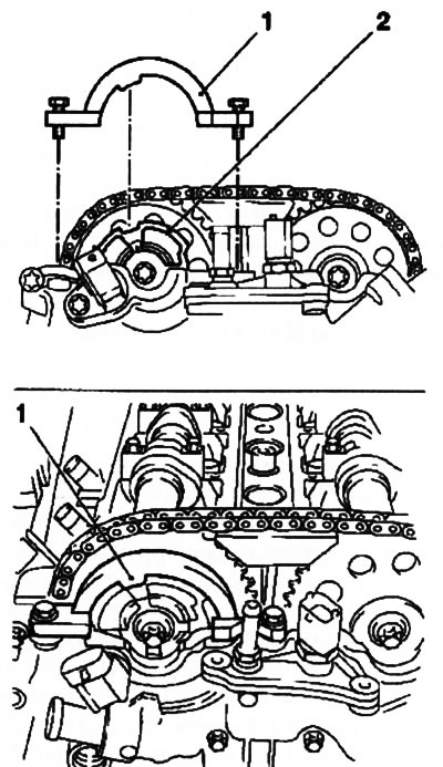
14. Turn out a bolt, having released a hole for installation of adaptation KM-955-1 (see illustration 6.14a) Using an open-end wrench, press the intake camshaft in the direction indicated by the arrow and fix the chain tensioner with KM-955-1, thereby loosening the chain tension.
Attention: When pressing/turning the camshafts, the key must only be installed on the hexagonal part of the shaft (see illustration 6.14b)!
6.14a Loose chain tension (Z10XEP engine): 1. Bolt holes for installing the fixing device; 2. Installing the KM-955-1 fixture | 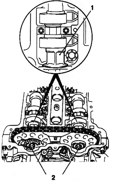
6.14b. Mounting bolts (2) camshaft sprockets: 1. Hexagonal part of the camshaft |
15. Holding the camshafts from turning by the hex part, loosen the fastening bolts of the sprockets of both shafts (see illustration 6.14b), and then unscrew them one by one and replace them with new ones. Tighten the bolts, but so that the intake camshaft sensor rotor (see illustration 6.12) could be turned by hand.
16. Install the KM-953 fixture, if necessary, tighten the camshafts with an open-end wrench - pay attention to the correct installation of the camshaft cams (see illustration 6.8). Remove the KM-955-1 tool.
17. Install the KM-954 fixture so that the protrusion of the fixture coincides with the notch of the rotor (see illustration 6.12) - If necessary, tighten the rotor by hand.
18. Screw in place the bolt of the hole for installing the KM-955-1 fixture and tighten with the required force. Tighten the mounting bolts of the camshaft sprockets with a force of 10 Nm - no more, then remove all adjusting devices.
19. Tighten the fastening bolts of the sprockets with a force of 50 Nm and another 60°- if necessary, use the help of an assistant, then smoothly turn the engine crankshaft 2 full turns and use the tools to check the TDC position - if the tools are not installed (see above), re-adjust the valve timing.
Installation
20. Installation of all removed components is made in an order, the return to an order of removal. When reassembling, use a new cylinder head cover gasket (see resist. illustration), apply a coat of sealant sealant (For example, «Silikon Blau RTV» Loctite) 2 mm thick at the joints of the cylinder head and timing cover.
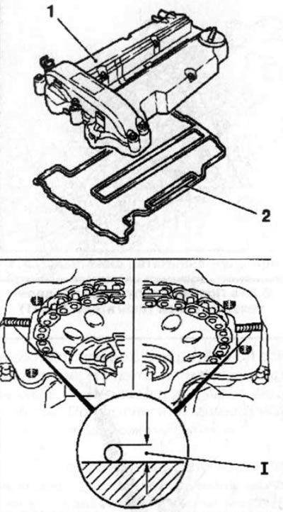
6.20. Pad (2) lids (1) cylinder heads: 1. Sealant layer thickness = 2mm
Attention: The cover must be installed within 10 minutes after applying the sealant! Don't forget to replace the crankshaft lock hole plug gasket.
Engines Z14XE/Z1 6XE/Z18XE
21. Remove the multirib belt cover (see Section 5).
22. Turn out 3 fixing bolts (see resist. illustration), separate the upper timing belt cover from the rear timing case and remove it.
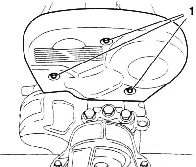
6.22. Mounting bolts (1) upper timing cover (engines Z14XE/Z16XE/Z18XE)
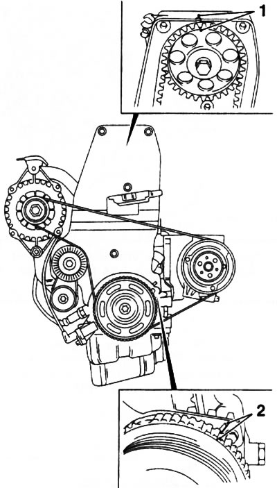
23. Rotate the crankshaft pulley in the direction of engine rotation (clockwise) so that the marks on the pulley and the engine block match (see resist. illustration) - at the same time, the marks on the gear wheels of the camshafts must also match. Now the piston of the first cylinder is at TDC of the compression stroke.
6.23. Setting TDC (engines Z14XE/Z1 6XE/Z1 8XE) - labels (2) crankshaft pulley and marks (1) camshaft gears must match
Note: If the camshaft marks are on the outer sides of the gears, turn the crankshaft one more turn.
If the marks of the timing gears do not match, it is necessary to adjust the distribution phases, for which it is necessary to remove the toothed belt (see Section 8).
24. At the end of the test, reinstall the removed components. Installation is in the reverse order. Before installing the upper timing cover, check its integrity and wipe it thoroughly inside and out.
Z16SE engine
25. Remove the V-belt cover (see Section 5).
26. Turn out 3 bolts and remove the top cover of the timing drive (see Section 8).
27. Turn the crankshaft pulley in the direction of engine rotation (clockwise) so that the marks on the pulley and the lower timing cover match (see resist. illustration) - at the same time, the marks on the camshaft gear and the rear timing cover must also match. Now the piston of the first cylinder is at TDC of the compression stroke.
6.27. When setting TDC marks (2) crankshaft pulley and marks (1) timing gear must match (Z16SE engine)
Note: If the camshaft mark is on the underside of the sprocket, turn the crankshaft one more turn.
If the marks of the timing gears do not match, it is necessary to adjust the distribution phases, for which it is necessary to remove the toothed belt (see Section 8).
Z13DT engine
28. Remove the multirib belt cover, (see Section 5).
29. Remove the fuel distribution line (see chapter 4).
30. Disconnect the electrical wiring connectors for glow plugs, injectors and camshaft sensor. Remove the 3 screws securing the cable duct and move it aside.
31. Remove 2 plugs from the camshaft housing (see illustration 6.31a). Clean the threads and screw the fixing pins into the holes (Opel-EN-46781) (see illustration 6.31b) - at the end of the installation, the flats on the outer side of the studs should be horizontal. Mark the studs if necessary.
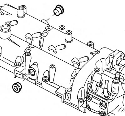
6.31a. Camshaft housing plugs (Z13DT engine) | 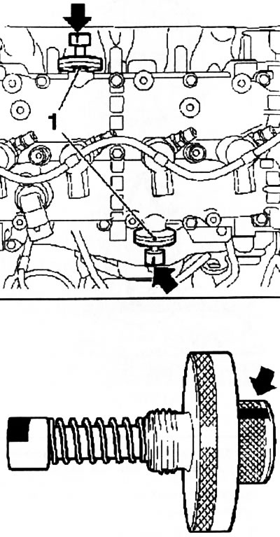
6.31b. Installation of fixing pins Opel-EN-46781 (Z13DT engine) - the arrows indicate the position of the flats |
32. Turn the crankshaft clockwise so that the spring-loaded fixing pins lock into place.
Attention: When turning the crankshaft, the assistant must ensure that the fixing pins do not turn!
33. Insert the Opel-EN-46785 pin into the special hole on the manual transmission (see resist. illustration), while rotating the crankshaft slightly back and forth to fit the pin into the hole in the flywheel. If the pin does not fit into the flywheel, the valve timing must be adjusted.
6.33. Installing the tool Opel-EN-46785 (Z13DT engine)
Y17DT engines (L) /Z17DTH
Note: The following is a description of the procedure for setting the first cylinder to TDC on the compression stroke using the Y17DT engine as an example. When performing this procedure on other engines, some additional steps will be required.
34. Loosen the fastening clamps and remove the flexible sleeve and the intermediate pipe of the engine air supply system (see chapter 4).
35. Remove the right front wheel (see chapter «Introduction»), place the suspended vehicle on stands.
36. Loosen the fastening clamps and remove the lower intermediate pipe of the intake duct (see chapter 4).
37. Remove the multirib belt (see Section 7).
38. Disconnect the generator wiring (see chapter 5).
39. Separate the cable duct and vacuum lines from the upper front timing cover. Turn out fixing bolts and remove the top cover of a gear belt.
Note: Bolts of various lengths are used to fasten the cover, remember or mark their installation position with a marker.
40. Turn the crankshaft until the holes on the gears of the camshaft and high pressure fuel pump are aligned with the holes on the engine housing and screw in the set bolts (see resist. illustration) M6 in the corresponding hole of the camshaft wheel and M8 in the injection pump drive wheel. Check the alignment of the marks - with the set bolts screwed in, the mark on the crankshaft pulley must match the pin on the oil pump cover.
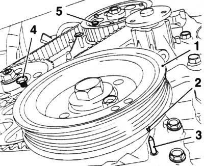
6.40. Setting TDC on the Y17DT engine: 1. Crankshaft pulley; 2. Crankshaft pulley mark; 3. Pin on the oil pump housing; 4. Installing bolt of the gear wheel of the injection pump (M8); 5. Camshaft gear set bolt (M6)
Note: With the crankshaft pulley removed, the mark on the toothed pulley should line up with the lug on the oil pump cover.
If the labels do not match, it is necessary to adjust the distribution phases (see Section 8) - First remove the toothed belt.
Visitor comments